

210
Electrochemical Supercapacitors for Energy Storage and Delivery
5.3.4 Current Collector Preparation
Metal foils of aluminum, copper and nickel with thicknesses between 20
and 80 μm are largely used as current collectors or electrode substrates due
to high conductance properties and low costs relative to gold or platinum.
During preparation, a foil should be etched by acid or other chemicals to
introduce higher surface area and irregularities along the surface to improve
the contact between the current collector and electrode layer. Three ways
to assemble the electrode layer and current collector are: (1) bind the previously prepared electrode layer film onto the current collector, (2) deposit the
electrode layer onto the current collector, and (3) spray the electrode layer
onto the current collector. If the electrode layer is not insufficiently adhered
to the current collector, a higher internal resistance will arise. After that, the
assembly obtained can be cut into a desired shape such as a pellet. If the
pellet is sufficiently dry, it will take several hours for the electrolyte to sufficiently saturate the pores of the electrodes and separator.
5.3.5 Single Cell Structure and Assembly
The design, assembly, and packaging of a supercapacitor depends strongly
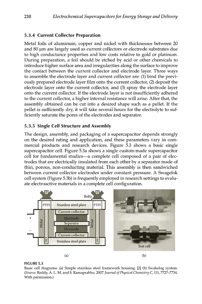
on the desired rating and application, and these parameters vary in commercial products and research devices. Figure 5.3 shows a basic single
supercapacitor cell. Figure 5.3a shows a single custom-made supercapacitor
cell for fundamental studies—a complete cell composed of a pair of electrodes that are electrically insulated from each other by a separator made of
thin, porous, non-conducting material. This assembly is then sandwiched
between current collector electrodes under constant pressure. A Swagelok
cell system (Figure 5.3b) is frequently employed in research settings to evaluate electroactive materials in a complete cell configuration.
PTFE
PTFE
Bolts
Stainless steel plate
Stainless steel plate
Mylar
+
_
Mylar
Current collector
Current collector
Electrode
Electrode
Separator
Test cell
(a)
(b)
FIGURE 5.3
Basic cell diagrams. (a) Simple stainless steel framework housing. [2] (b) Swakelog system.
(Source: Reddy, A. L. M. and S. Ramaprabhu. 2007. Journal of Physical Chemistry C, 111, 7727–7734.
With permission.)
Electrochemical Supercapacitors for Energy Storage and Delivery
5.3.4 Current Collector Preparation
Metal foils of aluminum, copper and nickel with thicknesses between 20
and 80 μm are largely used as current collectors or electrode substrates due
to high conductance properties and low costs relative to gold or platinum.
During preparation, a foil should be etched by acid or other chemicals to
introduce higher surface area and irregularities along the surface to improve
the contact between the current collector and electrode layer. Three ways
to assemble the electrode layer and current collector are: (1) bind the previously prepared electrode layer film onto the current collector, (2) deposit the
electrode layer onto the current collector, and (3) spray the electrode layer
onto the current collector. If the electrode layer is not insufficiently adhered
to the current collector, a higher internal resistance will arise. After that, the
assembly obtained can be cut into a desired shape such as a pellet. If the
pellet is sufficiently dry, it will take several hours for the electrolyte to sufficiently saturate the pores of the electrodes and separator.
5.3.5 Single Cell Structure and Assembly
The design, assembly, and packaging of a supercapacitor depends strongly
on the desired rating and application, and these parameters vary in commercial products and research devices. Figure 5.3 shows a basic single
supercapacitor cell. Figure 5.3a shows a single custom-made supercapacitor
cell for fundamental studies—a complete cell composed of a pair of electrodes that are electrically insulated from each other by a separator made of
thin, porous, non-conducting material. This assembly is then sandwiched
between current collector electrodes under constant pressure. A Swagelok
cell system (Figure 5.3b) is frequently employed in research settings to evaluate electroactive materials in a complete cell configuration.
PTFE
PTFE
Bolts
Stainless steel plate
Stainless steel plate
Mylar
+
_
Mylar
Current collector
Current collector
Electrode
Electrode
Separator
Test cell
(a)
(b)
FIGURE 5.3
Basic cell diagrams. (a) Simple stainless steel framework housing. [2] (b) Swakelog system.
(Source: Reddy, A. L. M. and S. Ramaprabhu. 2007. Journal of Physical Chemistry C, 111, 7727–7734.
With permission.)