

144
Electrochemical Supercapacitors for Energy Storage and Delivery
surface area analysis is conducted with gas that can penetrate pores that
are too small for ions so blocked areas may exist. Blocked pores or tightly
bound planes prevent ions from organizing at the surface and can be due
to poor long range order or collapsed channels within the electrode. To prevent blockages, materials are often designed with periodic structures or
large macroporous channels. Chemical activation with KOH is another way
to increase surface area by unblocking pores and creating new ones in the
carbon materials. However, if the macropores are too big, they become macroscopic voids that detract from otherwise usable surface area.
4.2.5 Pore Structure for EDLC Design
In the past, desirable surface area encompassed macroporous structures for
the increased flow of ions and mesoporous structures to maximize surface
area. Ions were viewed as restricted from entering micropores. The comparably large solvent cage around the ions blocked entrance into the smaller
pores [9,10]. Recent discoveries by Chmiolo et al. and Huang et al. [11–15]
have shown that this is not entirely true. Figure 4.3 shows that as pore size
decreases into the sub-5 nm range, capacitance also decreases.
The standard parallel plate model (applicable to region IV in Figure 4.3) of
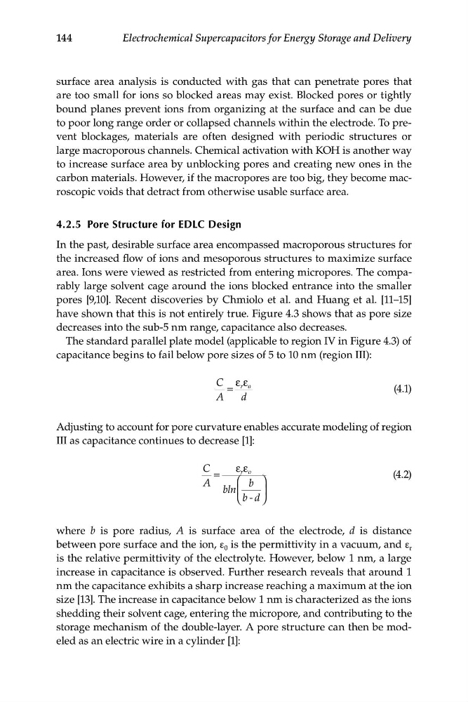
capacitance begins to fail below pore sizes of 5 to 10 nm (region III):
ε ε
C
r o
=
(4.1)
A
d
Adjusting to account for pore curvature enables accurate modeling of region
III as capacitance continues to decrease [1]:
C
ε ε
=
r o
(4.2)
A
⎛ b ⎞
bln ⎜
⎟
⎝ b - d ⎠
where b is pore radius, A is surface area of the electrode, d is distance
between pore surface and the ion, ε 0 is the permittivity in a vacuum, and ε r
is the relative permittivity of the electrolyte. However, below 1 nm, a large
increase in capacitance is observed. Further research reveals that around 1
nm the capacitance exhibits a sharp increase reaching a maximum at the ion
size [13]. The increase in capacitance below 1 nm is characterized as the ions
shedding their solvent cage, entering the micropore, and contributing to the
storage mechanism of the double-layer. A pore structure can then be modeled as an electric wire in a cylinder [1]:
Electrochemical Supercapacitors for Energy Storage and Delivery
surface area analysis is conducted with gas that can penetrate pores that
are too small for ions so blocked areas may exist. Blocked pores or tightly
bound planes prevent ions from organizing at the surface and can be due
to poor long range order or collapsed channels within the electrode. To prevent blockages, materials are often designed with periodic structures or
large macroporous channels. Chemical activation with KOH is another way
to increase surface area by unblocking pores and creating new ones in the
carbon materials. However, if the macropores are too big, they become macroscopic voids that detract from otherwise usable surface area.
4.2.5 Pore Structure for EDLC Design
In the past, desirable surface area encompassed macroporous structures for
the increased flow of ions and mesoporous structures to maximize surface
area. Ions were viewed as restricted from entering micropores. The comparably large solvent cage around the ions blocked entrance into the smaller
pores [9,10]. Recent discoveries by Chmiolo et al. and Huang et al. [11–15]
have shown that this is not entirely true. Figure 4.3 shows that as pore size
decreases into the sub-5 nm range, capacitance also decreases.
The standard parallel plate model (applicable to region IV in Figure 4.3) of
capacitance begins to fail below pore sizes of 5 to 10 nm (region III):
ε ε
C
r o
=
(4.1)
A
d
Adjusting to account for pore curvature enables accurate modeling of region
III as capacitance continues to decrease [1]:
C
ε ε
=
r o
(4.2)
A
⎛ b ⎞
bln ⎜
⎟
⎝ b - d ⎠
where b is pore radius, A is surface area of the electrode, d is distance
between pore surface and the ion, ε 0 is the permittivity in a vacuum, and ε r
is the relative permittivity of the electrolyte. However, below 1 nm, a large
increase in capacitance is observed. Further research reveals that around 1
nm the capacitance exhibits a sharp increase reaching a maximum at the ion
size [13]. The increase in capacitance below 1 nm is characterized as the ions
shedding their solvent cage, entering the micropore, and contributing to the
storage mechanism of the double-layer. A pore structure can then be modeled as an electric wire in a cylinder [1]: