

0 min
100
80
60
40
20
0
Z˝/Ohm
60 min
240 min
60
80
100
120
140
160
Z´/Ohm
126
Electrochemical Supercapacitors for Energy Storage and Delivery
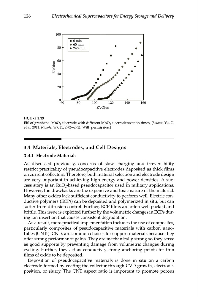
FIGURE 3.15
EIS of graphene–MnO 2 electrode with different MnO 2 electrodeposition times. (Source: Yu, G.
et al. 2011. Nanoletters, 11, 2905–2911. With permission.)
3.4 Materials, Electrodes, and Cell Designs
3.4.1 Electrode Materials
As discussed previously, concerns of slow charging and irreversibility
restrict practicality of pseudocapacitive electrodes deposited as thick films
on current collectors. Therefore, both material selection and electrode design
are very important in achieving high energy and power densities. A success story is an RuO 2 -based pseudocapacitor used in military applications.
However, the drawbacks are the expensive and toxic nature of the material.
Many other oxides lack sufficient conductivity to perform well. Electric conductive polymers (ECPs) can be deposited and polymerized in situ, but can
suffer from diffusion control. Further, ECP films are often well packed and
brittle. This issue is exploited further by the volumetric changes in ECPs during ion insertion that causes consistent degradation.
As a result, more practical implementation includes the use of composites,
particularly composites of pseudocapacitive materials with carbon nanotubes (CNTs). CNTs are common choices for support materials because they
offer strong performance gains. They are mechanically strong so they serve
as good supports by preventing damage from volumetric changes during
cycling. Further, they act as conductive, strong anchoring points for thin
films of oxide to be deposited.
Deposition of pseudocapacitive materials is done in situ on a carbon
electrode formed by coating the collector through CVD growth, electrodeposition, or slurry. The CNT aspect ratio is important to promote porous
100
80
60
40
20
0
Z˝/Ohm
60 min
240 min
60
80
100
120
140
160
Z´/Ohm
126
Electrochemical Supercapacitors for Energy Storage and Delivery
FIGURE 3.15
EIS of graphene–MnO 2 electrode with different MnO 2 electrodeposition times. (Source: Yu, G.
et al. 2011. Nanoletters, 11, 2905–2911. With permission.)
3.4 Materials, Electrodes, and Cell Designs
3.4.1 Electrode Materials
As discussed previously, concerns of slow charging and irreversibility
restrict practicality of pseudocapacitive electrodes deposited as thick films
on current collectors. Therefore, both material selection and electrode design
are very important in achieving high energy and power densities. A success story is an RuO 2 -based pseudocapacitor used in military applications.
However, the drawbacks are the expensive and toxic nature of the material.
Many other oxides lack sufficient conductivity to perform well. Electric conductive polymers (ECPs) can be deposited and polymerized in situ, but can
suffer from diffusion control. Further, ECP films are often well packed and
brittle. This issue is exploited further by the volumetric changes in ECPs during ion insertion that causes consistent degradation.
As a result, more practical implementation includes the use of composites,
particularly composites of pseudocapacitive materials with carbon nanotubes (CNTs). CNTs are common choices for support materials because they
offer strong performance gains. They are mechanically strong so they serve
as good supports by preventing damage from volumetric changes during
cycling. Further, they act as conductive, strong anchoring points for thin
films of oxide to be deposited.
Deposition of pseudocapacitive materials is done in situ on a carbon
electrode formed by coating the collector through CVD growth, electrodeposition, or slurry. The CNT aspect ratio is important to promote porous