

10.2 The LED Aging Test and an Aging Mechanism
215
the protective material, causing the degradation of material and device performance.
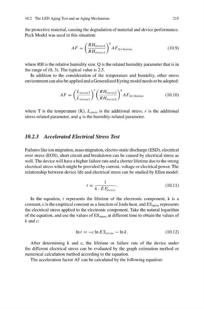
Peck Model was used in this situation:
AF =
R H stress2
R H stress1
q
AF Arr henius
(10.9)
where RH is the relative humidity size. Q is the related humidity parameter that is in
the range of (0, 3). The typical value is 2.5.
In addition to the consideration of the temperature and humidity, other stress
environment can also be applied and a Generalized Eyring model needs to be adopted:
AF =
L stress2
L stress1
r
R H stress2
R H stress1
q
AF Arr henius
(10.10)
where T is the temperature (K), L stress is the additional stress, r is the additional
stress-related parameter, and q is the humidity-related parameter.
10.2.3 Accelerated Electrical Stress Test
Failures like ion migration, mass migration, electro-static discharge (ESD), electrical
over stress (EOS), short circuit and breakdown can be caused by electrical stress as
well. The device will have a higher failure rate and a shorter lifetime due to the strong
electrical stress which might be provided by current, voltage or electrical power. The
relationship between device life and electrical stress can be studied by Ellen model:
t =
1
k · E S
c
stress
.
(10.11)
In the equation, t represents the lifetime of the electronic component, k is a
constant, c is the empirical constant as a function of Joule heat, and ES stress represents
the electrical stress applied to the electronic component. Take the natural logarithm
of the equation, and use the values of ES stress at different time to obtain the values of
k and c:
ln t = −c ln E S stress − ln k.
(10.12)
After determining k and c, the lifetime or failure rate of the device under
the different electrical stress can be evaluated by the graph estimation method or
numerical calculation method according to the equation.
The acceleration factor AF can be calculated by the following equation:
215
the protective material, causing the degradation of material and device performance.
Peck Model was used in this situation:
AF =
R H stress2
R H stress1
q
AF Arr henius
(10.9)
where RH is the relative humidity size. Q is the related humidity parameter that is in
the range of (0, 3). The typical value is 2.5.
In addition to the consideration of the temperature and humidity, other stress
environment can also be applied and a Generalized Eyring model needs to be adopted:
AF =
L stress2
L stress1
r
R H stress2
R H stress1
q
AF Arr henius
(10.10)
where T is the temperature (K), L stress is the additional stress, r is the additional
stress-related parameter, and q is the humidity-related parameter.
10.2.3 Accelerated Electrical Stress Test
Failures like ion migration, mass migration, electro-static discharge (ESD), electrical
over stress (EOS), short circuit and breakdown can be caused by electrical stress as
well. The device will have a higher failure rate and a shorter lifetime due to the strong
electrical stress which might be provided by current, voltage or electrical power. The
relationship between device life and electrical stress can be studied by Ellen model:
t =
1
k · E S
c
stress
.
(10.11)
In the equation, t represents the lifetime of the electronic component, k is a
constant, c is the empirical constant as a function of Joule heat, and ES stress represents
the electrical stress applied to the electronic component. Take the natural logarithm
of the equation, and use the values of ES stress at different time to obtain the values of
k and c:
ln t = −c ln E S stress − ln k.
(10.12)
After determining k and c, the lifetime or failure rate of the device under
the different electrical stress can be evaluated by the graph estimation method or
numerical calculation method according to the equation.
The acceleration factor AF can be calculated by the following equation: