

176
8 III-Nitride LED Chip Fabrication Techniques
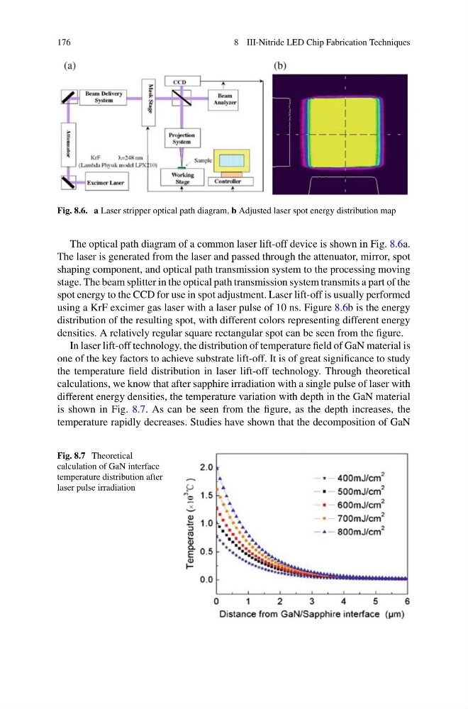
Fig. 8.6. a Laser stripper optical path diagram, b Adjusted laser spot energy distribution map
The optical path diagram of a common laser lift-off device is shown in Fig. 8.6a.
The laser is generated from the laser and passed through the attenuator, mirror, spot
shaping component, and optical path transmission system to the processing moving
stage. The beam splitter in the optical path transmission system transmits a part of the
spot energy to the CCD for use in spot adjustment. Laser lift-off is usually performed
using a KrF excimer gas laser with a laser pulse of 10 ns. Figure 8.6b is the energy
distribution of the resulting spot, with different colors representing different energy
densities. A relatively regular square rectangular spot can be seen from the figure.
In laser lift-off technology, the distribution of temperature field of GaN material is
one of the key factors to achieve substrate lift-off. It is of great significance to study
the temperature field distribution in laser lift-off technology. Through theoretical
calculations, we know that after sapphire irradiation with a single pulse of laser with
different energy densities, the temperature variation with depth in the GaN material
is shown in Fig. 8.7. As can be seen from the figure, as the depth increases, the
temperature rapidly decreases. Studies have shown that the decomposition of GaN
Fig. 8.7 Theoretical
calculation of GaN interface
temperature distribution after
laser pulse irradiation
8 III-Nitride LED Chip Fabrication Techniques
Fig. 8.6. a Laser stripper optical path diagram, b Adjusted laser spot energy distribution map
The optical path diagram of a common laser lift-off device is shown in Fig. 8.6a.
The laser is generated from the laser and passed through the attenuator, mirror, spot
shaping component, and optical path transmission system to the processing moving
stage. The beam splitter in the optical path transmission system transmits a part of the
spot energy to the CCD for use in spot adjustment. Laser lift-off is usually performed
using a KrF excimer gas laser with a laser pulse of 10 ns. Figure 8.6b is the energy
distribution of the resulting spot, with different colors representing different energy
densities. A relatively regular square rectangular spot can be seen from the figure.
In laser lift-off technology, the distribution of temperature field of GaN material is
one of the key factors to achieve substrate lift-off. It is of great significance to study
the temperature field distribution in laser lift-off technology. Through theoretical
calculations, we know that after sapphire irradiation with a single pulse of laser with
different energy densities, the temperature variation with depth in the GaN material
is shown in Fig. 8.7. As can be seen from the figure, as the depth increases, the
temperature rapidly decreases. Studies have shown that the decomposition of GaN
Fig. 8.7 Theoretical
calculation of GaN interface
temperature distribution after
laser pulse irradiation