

6.4 Structure Design and Fabrication of UV LEDs
107
(a)
(c)
(b)
(d)
(e)
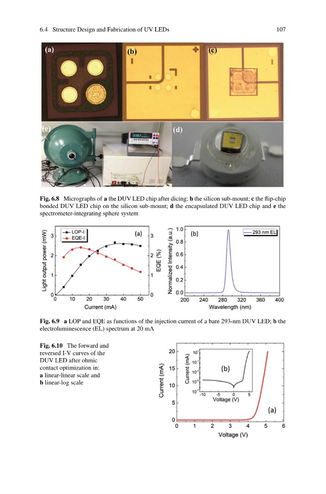
Fig. 6.8 Micrographs of a the DUV LED chip after dicing; b the silicon sub-mount; c the flip-chip
bonded DUV LED chip on the silicon sub-mount; d the encapsulated DUV LED chip and e the
spectrometer-integrating sphere system
Fig. 6.9 a LOP and EQE as functions of the injection current of a bare 293-nm DUV LED; b the
electroluminescence (EL) spectrum at 20 mA
Fig. 6.10 The forward and
reversed I-V curves of the
DUV LED after ohmic
contact optimization in:
a linear-linear scale and
b linear-log scale
107
(a)
(c)
(b)
(d)
(e)
Fig. 6.8 Micrographs of a the DUV LED chip after dicing; b the silicon sub-mount; c the flip-chip
bonded DUV LED chip on the silicon sub-mount; d the encapsulated DUV LED chip and e the
spectrometer-integrating sphere system
Fig. 6.9 a LOP and EQE as functions of the injection current of a bare 293-nm DUV LED; b the
electroluminescence (EL) spectrum at 20 mA
Fig. 6.10 The forward and
reversed I-V curves of the
DUV LED after ohmic
contact optimization in:
a linear-linear scale and
b linear-log scale