

118
M. Miyata and S. Tsuzuki
C1
C2 1 B1
C3 2 B2 1 A1
C4 3 B3 2 A2 1 D1
X1
X2 1 Ba
X3 2 Bb 1 90
C1 3 B1 2 A1 1 D1
X1
X3
C1
X2
C1
C2
C3
C4
a
c
d
b
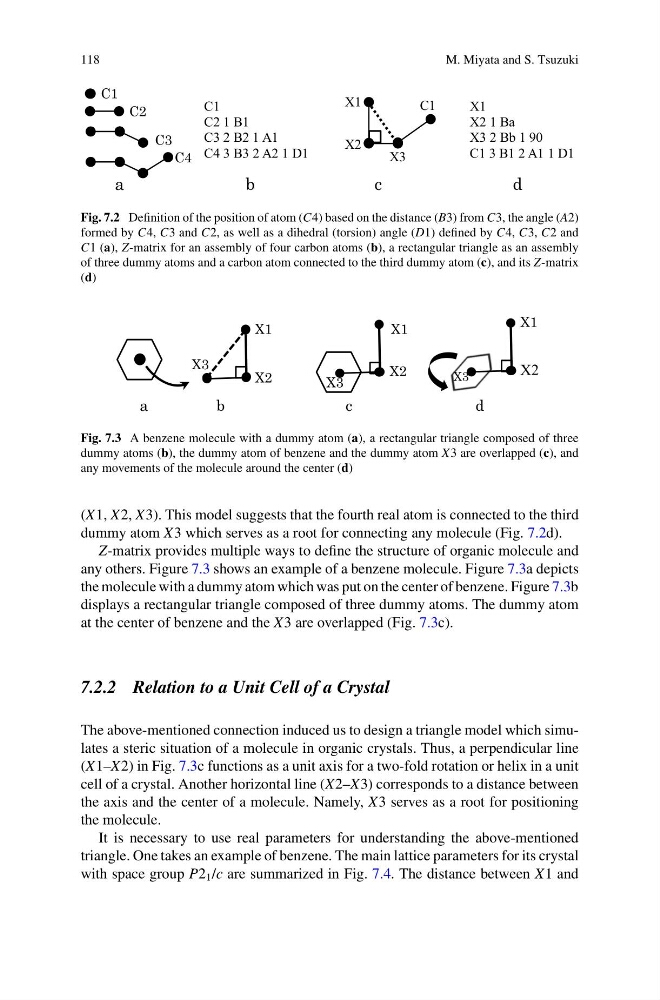
Fig. 7.2 Definition of the position of atom (C4) based on the distance (B3) from C3, the angle (A2)
formed by C4, C3 and C2, as well as a dihedral (torsion) angle (D1) defined by C4, C3, C2 and
C1 (a), Z-matrix for an assembly of four carbon atoms (b), a rectangular triangle as an assembly
of three dummy atoms and a carbon atom connected to the third dummy atom (c), and its Z-matrix
(d)
c
a
d
b
X3
X2
X1
X2
X3
X1
X2
X3
X1
Fig. 7.3 A benzene molecule with a dummy atom (a), a rectangular triangle composed of three
dummy atoms (b), the dummy atom of benzene and the dummy atom X3 are overlapped (c), and
any movements of the molecule around the center (d)
(X1, X2, X3). This model suggests that the fourth real atom is connected to the third
dummy atom X3 which serves as a root for connecting any molecule (Fig. 7.2d).
Z-matrix provides multiple ways to define the structure of organic molecule and
any others. Figure 7.3 shows an example of a benzene molecule. Figure 7.3a depicts
the molecule with a dummy atom which was put on the center of benzene. Figure 7.3b
displays a rectangular triangle composed of three dummy atoms. The dummy atom
at the center of benzene and the X3 are overlapped (Fig. 7.3c).
7.2.2 Relation to a Unit Cell of a Crystal
The above-mentioned connection induced us to design a triangle model which simulates a steric situation of a molecule in organic crystals. Thus, a perpendicular line
(X1–X2) in Fig. 7.3c functions as a unit axis for a two-fold rotation or helix in a unit
cell of a crystal. Another horizontal line (X2–X3) corresponds to a distance between
the axis and the center of a molecule. Namely, X3 serves as a root for positioning
the molecule.
It is necessary to use real parameters for understanding the above-mentioned
triangle. One takes an example of benzene. The main lattice parameters for its crystal
with space group P2 1 /c are summarized in Fig. 7.4. The distance between X1 and
M. Miyata and S. Tsuzuki
C1
C2 1 B1
C3 2 B2 1 A1
C4 3 B3 2 A2 1 D1
X1
X2 1 Ba
X3 2 Bb 1 90
C1 3 B1 2 A1 1 D1
X1
X3
C1
X2
C1
C2
C3
C4
a
c
d
b
Fig. 7.2 Definition of the position of atom (C4) based on the distance (B3) from C3, the angle (A2)
formed by C4, C3 and C2, as well as a dihedral (torsion) angle (D1) defined by C4, C3, C2 and
C1 (a), Z-matrix for an assembly of four carbon atoms (b), a rectangular triangle as an assembly
of three dummy atoms and a carbon atom connected to the third dummy atom (c), and its Z-matrix
(d)
c
a
d
b
X3
X2
X1
X2
X3
X1
X2
X3
X1
Fig. 7.3 A benzene molecule with a dummy atom (a), a rectangular triangle composed of three
dummy atoms (b), the dummy atom of benzene and the dummy atom X3 are overlapped (c), and
any movements of the molecule around the center (d)
(X1, X2, X3). This model suggests that the fourth real atom is connected to the third
dummy atom X3 which serves as a root for connecting any molecule (Fig. 7.2d).
Z-matrix provides multiple ways to define the structure of organic molecule and
any others. Figure 7.3 shows an example of a benzene molecule. Figure 7.3a depicts
the molecule with a dummy atom which was put on the center of benzene. Figure 7.3b
displays a rectangular triangle composed of three dummy atoms. The dummy atom
at the center of benzene and the X3 are overlapped (Fig. 7.3c).
7.2.2 Relation to a Unit Cell of a Crystal
The above-mentioned connection induced us to design a triangle model which simulates a steric situation of a molecule in organic crystals. Thus, a perpendicular line
(X1–X2) in Fig. 7.3c functions as a unit axis for a two-fold rotation or helix in a unit
cell of a crystal. Another horizontal line (X2–X3) corresponds to a distance between
the axis and the center of a molecule. Namely, X3 serves as a root for positioning
the molecule.
It is necessary to use real parameters for understanding the above-mentioned
triangle. One takes an example of benzene. The main lattice parameters for its crystal
with space group P2 1 /c are summarized in Fig. 7.4. The distance between X1 and