

48
2 – Methods and techniques
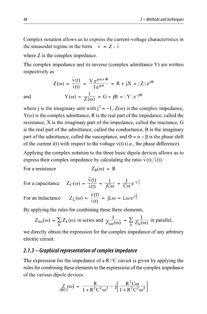
Complex notation allows us to express the current-voltage characteristics in
the sinusoidal regime in the form v = Z # i
where Z is the complex impedance.
The complex impedance and its inverse (complex admittance Y) are written
respectively as
Z( )
i(t)
v(t)
I e
V e
R jX |Z | e
j t
j t
j
ω =
=
= +
=
ω
ω Φ
Φ
+
and
Y( )
Z( )
1
G jB |Y | e
j
ω
ω
=
= +
=
Φ
−
where j is the imaginary unit with j
2 = −1, Z(ω) is the complex impedance,
Y(ω) is the complex admittance, R is the real part of the impedance, called the
resistance, X is the imaginary part of the impedance, called the reactance, G
is the real part of the admittance, called the conductance, B is the imaginary
part of the admittance, called the susceptance, and Φ = α − β is the phase shift
of the current i(t) with respect to the voltage v(t) (i.e., the phase difference).
Applying the complex notation to the three basic dipole devices allows us to
express their complex impedance by calculating the ratio ( ) ( )
v t i t .
For a resistance
Z R (ω) = R
For a capacitance Z ( )
i(t)
v(t)
jC
1
C
1
e
C
j 2
ω
ω
ω
=
=
=
−
r
For an inductance
Z ( )
i(t)
v(t)
jL
L e
L
j 2
ω
ω
ω
=
=
=
r
By applying the rules for combining these three elements,
( )
( )
Z
Z
tot
k
k
ω
ω
= /
in series and
( )
( )
1
1
Z
Z
tot
k
k
ω
ω
= /
in parallel,
we directly obtain the expression for the complex impedance of any arbitrary
electric circuit.
2.1.3 – Graphical representation of complex impedance
The expression for the impedance of a R //C circuit is given by applying the
rules for combining these elements to the expressions of the complex impedance
of the various dipole devices
Z ( )
1 R C
R
j 1 R C
R C
(RC)
2 2 2
2 2 2
2
ω
ω
ω
ω
= +
−
+
;
E
2 – Methods and techniques
Complex notation allows us to express the current-voltage characteristics in
the sinusoidal regime in the form v = Z # i
where Z is the complex impedance.
The complex impedance and its inverse (complex admittance Y) are written
respectively as
Z( )
i(t)
v(t)
I e
V e
R jX |Z | e
j t
j t
j
ω =
=
= +
=
ω
ω Φ
Φ
+
and
Y( )
Z( )
1
G jB |Y | e
j
ω
ω
=
= +
=
Φ
−
where j is the imaginary unit with j
2 = −1, Z(ω) is the complex impedance,
Y(ω) is the complex admittance, R is the real part of the impedance, called the
resistance, X is the imaginary part of the impedance, called the reactance, G
is the real part of the admittance, called the conductance, B is the imaginary
part of the admittance, called the susceptance, and Φ = α − β is the phase shift
of the current i(t) with respect to the voltage v(t) (i.e., the phase difference).
Applying the complex notation to the three basic dipole devices allows us to
express their complex impedance by calculating the ratio ( ) ( )
v t i t .
For a resistance
Z R (ω) = R
For a capacitance Z ( )
i(t)
v(t)
jC
1
C
1
e
C
j 2
ω
ω
ω
=
=
=
−
r
For an inductance
Z ( )
i(t)
v(t)
jL
L e
L
j 2
ω
ω
ω
=
=
=
r
By applying the rules for combining these three elements,
( )
( )
Z
Z
tot
k
k
ω
ω
= /
in series and
( )
( )
1
1
Z
Z
tot
k
k
ω
ω
= /
in parallel,
we directly obtain the expression for the complex impedance of any arbitrary
electric circuit.
2.1.3 – Graphical representation of complex impedance
The expression for the impedance of a R //C circuit is given by applying the
rules for combining these elements to the expressions of the complex impedance
of the various dipole devices
Z ( )
1 R C
R
j 1 R C
R C
(RC)
2 2 2
2 2 2
2
ω
ω
ω
ω
= +
−
+
;
E