

Terahertz Radiators Based on Silicon Carbide Avalanche Transit …
27
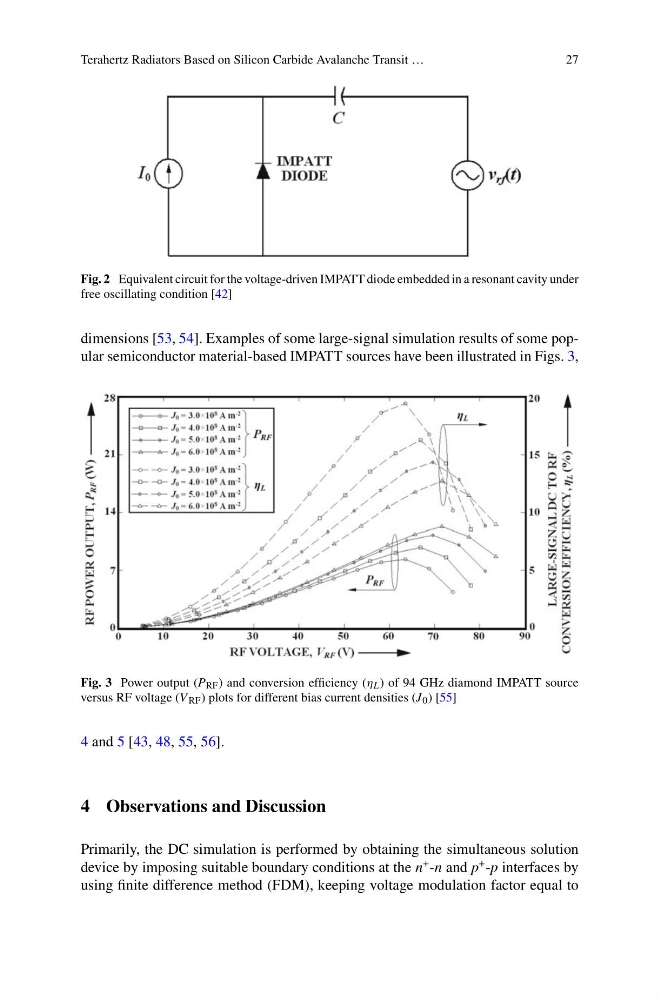
Fig. 2 Equivalent circuit for the voltage-driven IMPATT diode embedded in a resonant cavity under
free oscillating condition [42]
dimensions [53, 54]. Examples of some large-signal simulation results of some popular semiconductor material-based IMPATT sources have been illustrated in Figs. 3,
Fig. 3 Power output (P RF ) and conversion efficiency (η L ) of 94 GHz diamond IMPATT source
versus RF voltage (V RF ) plots for different bias current densities (J 0 ) [55]
4 and 5 [43, 48, 55, 56].
4 Observations and Discussion
Primarily, the DC simulation is performed by obtaining the simultaneous solution
device by imposing suitable boundary conditions at the n
+ -n and p
+ -p interfaces by
using finite difference method (FDM), keeping voltage modulation factor equal to
27
Fig. 2 Equivalent circuit for the voltage-driven IMPATT diode embedded in a resonant cavity under
free oscillating condition [42]
dimensions [53, 54]. Examples of some large-signal simulation results of some popular semiconductor material-based IMPATT sources have been illustrated in Figs. 3,
Fig. 3 Power output (P RF ) and conversion efficiency (η L ) of 94 GHz diamond IMPATT source
versus RF voltage (V RF ) plots for different bias current densities (J 0 ) [55]
4 and 5 [43, 48, 55, 56].
4 Observations and Discussion
Primarily, the DC simulation is performed by obtaining the simultaneous solution
device by imposing suitable boundary conditions at the n
+ -n and p
+ -p interfaces by
using finite difference method (FDM), keeping voltage modulation factor equal to