

Data Transmission with Terahertz Communication Systems
127
• Second, two QPSK points
x
(s)
2k , x
(s)
2k+1
are converted to two 16 QAM points
d
i SS , s, k
, d
i SS , s, P(k)
by multiplication on mapping matrix Q as follows:
d
i SS , s, k
d
i SS , s, P(k)
=
1
√
5
1 2
−2 1
=Q
·
x
(s)
2k
x
(s)
2k+1
(4)
where index P(k) is defined in the range N SD /2 to N SD /2 − 1. The qth modulated
data block of i SS th spatial stream is mapped to N SD data subcarriers of qth OFDM
symbol of i SS th spatial stream.
Specifically, when QPSK modulation is chosen, it gives a constant amplitude
waveform with 0 dB PAPR [22]. In practice, however, single carrier modulation is
typically followed by a time-dispersive transmit pulse shaping filter that is more localized in frequency domain, to reduce out of band (OOB) leakage and meet adjacent
channel leakage ratio (ACLR) requirements.
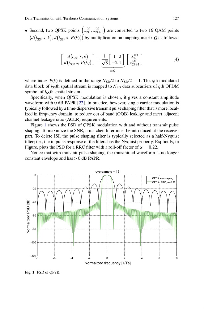
Figure 1 shows the PSD of QPSK modulation with and without transmit pulse
shaping. To maximize the SNR, a matched filter must be introduced at the receiver
part. To delete ISI, the pulse shaping filter is typically selected as a half-Nyquist
filter; i.e., the impulse response of the filters has the Nyquist property. Explicitly, in
Figure, plots the PSD for a RRC filter with a roll-off factor of α = 0.22.
Notice that with transmit pulse shaping, the transmitted waveform is no longer
constant envelope and has > 0 dB PAPR.
-8
-6
-4
-2
0
2
4
6
8
-120
-100
-80
-60
-40
-20
0
Normalized frequency [1/Ts]
Normalized PSD [dB]
oversample = 16
QPSK w/o shaping
QPSK+RRC, α=0.22
Fig. 1 PSD of QPSK
127
• Second, two QPSK points
x
(s)
2k , x
(s)
2k+1
are converted to two 16 QAM points
d
i SS , s, k
, d
i SS , s, P(k)
by multiplication on mapping matrix Q as follows:
d
i SS , s, k
d
i SS , s, P(k)
=
1
√
5
1 2
−2 1
=Q
·
x
(s)
2k
x
(s)
2k+1
(4)
where index P(k) is defined in the range N SD /2 to N SD /2 − 1. The qth modulated
data block of i SS th spatial stream is mapped to N SD data subcarriers of qth OFDM
symbol of i SS th spatial stream.
Specifically, when QPSK modulation is chosen, it gives a constant amplitude
waveform with 0 dB PAPR [22]. In practice, however, single carrier modulation is
typically followed by a time-dispersive transmit pulse shaping filter that is more localized in frequency domain, to reduce out of band (OOB) leakage and meet adjacent
channel leakage ratio (ACLR) requirements.
Figure 1 shows the PSD of QPSK modulation with and without transmit pulse
shaping. To maximize the SNR, a matched filter must be introduced at the receiver
part. To delete ISI, the pulse shaping filter is typically selected as a half-Nyquist
filter; i.e., the impulse response of the filters has the Nyquist property. Explicitly, in
Figure, plots the PSD for a RRC filter with a roll-off factor of α = 0.22.
Notice that with transmit pulse shaping, the transmitted waveform is no longer
constant envelope and has > 0 dB PAPR.
-8
-6
-4
-2
0
2
4
6
8
-120
-100
-80
-60
-40
-20
0
Normalized frequency [1/Ts]
Normalized PSD [dB]
oversample = 16
QPSK w/o shaping
QPSK+RRC, α=0.22
Fig. 1 PSD of QPSK