

29 Femtosecond Pump-Probe Microspectroscopy …
497
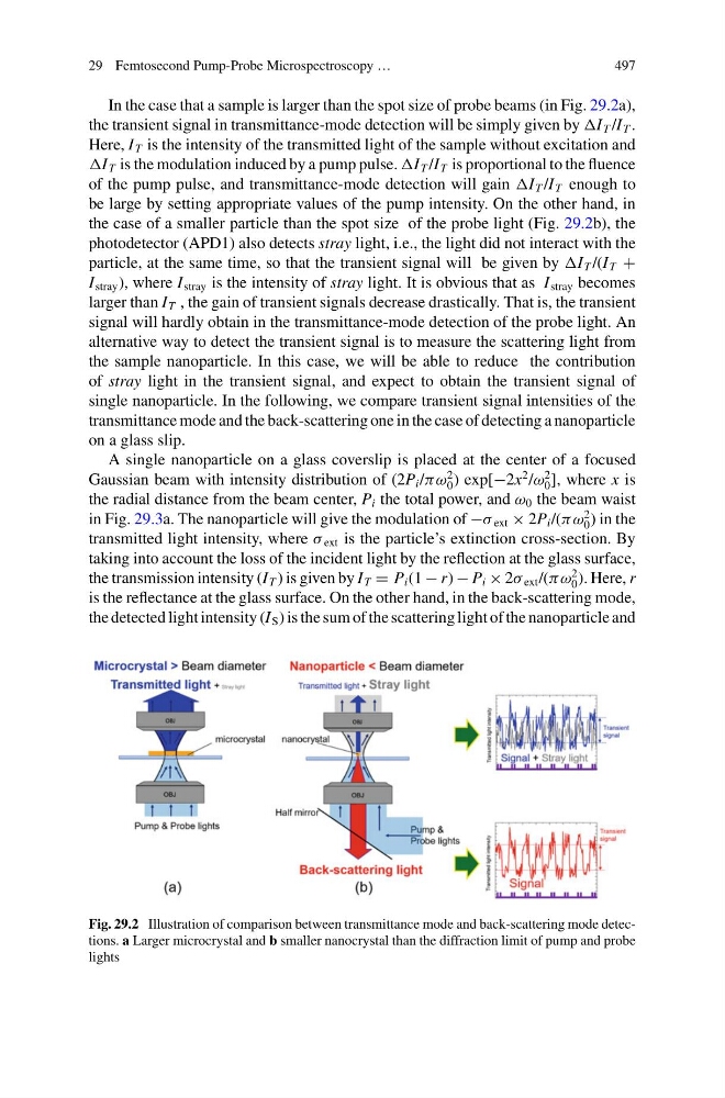
In the case that a sample is larger than the spot size of probe beams (in Fig. 29.2a),
the transient signal in transmittance-mode detection will be simply given by I T /I T .
Here, I T is the intensity of the transmitted light of the sample without excitation and
I T is the modulation induced by a pump pulse. I T /I T is proportional to the fluence
of the pump pulse, and transmittance-mode detection will gain I T /I T enough to
be large by setting appropriate values of the pump intensity. On the other hand, in
the case of a smaller particle than the spot size of the probe light (Fig. 29.2b), the
photodetector (APD1) also detects stray light, i.e., the light did not interact with the
particle, at the same time, so that the transient signal will be given by I T /(I T +
I stray ), where I stray is the intensity of stray light. It is obvious that as I stray becomes
larger than I T , the gain of transient signals decrease drastically. That is, the transient
signal will hardly obtain in the transmittance-mode detection of the probe light. An
alternative way to detect the transient signal is to measure the scattering light from
the sample nanoparticle. In this case, we will be able to reduce the contribution
of stray light in the transient signal, and expect to obtain the transient signal of
single nanoparticle. In the following, we compare transient signal intensities of the
transmittance mode and the back-scattering one in the case of detecting a nanoparticle
on a glass slip.
A single nanoparticle on a glass coverslip is placed at the center of a focused
Gaussian beam with intensity distribution of (2P i /πω
2
0 ) exp[−2x
2 /ω
2
0 ], where x is
the radial distance from the beam center, P i the total power, and ω 0 the beam waist
in Fig. 29.3a. The nanoparticle will give the modulation of −σ ext × 2P i /(πω
2
0 ) in the
transmitted light intensity, where σ ext is the particle’s extinction cross-section. By
taking into account the loss of the incident light by the reflection at the glass surface,
the transmission intensity (I T ) is given by I T = P i (1 − r) − P i × 2σ ext /(πω
2
0 ). Here, r
is the reflectance at the glass surface. On the other hand, in the back-scattering mode,
the detected light intensity (I S ) is the sum of the scattering light of the nanoparticle and
Fig. 29.2 Illustration of comparison between transmittance mode and back-scattering mode detections. a Larger microcrystal and b smaller nanocrystal than the diffraction limit of pump and probe
lights
497
In the case that a sample is larger than the spot size of probe beams (in Fig. 29.2a),
the transient signal in transmittance-mode detection will be simply given by I T /I T .
Here, I T is the intensity of the transmitted light of the sample without excitation and
I T is the modulation induced by a pump pulse. I T /I T is proportional to the fluence
of the pump pulse, and transmittance-mode detection will gain I T /I T enough to
be large by setting appropriate values of the pump intensity. On the other hand, in
the case of a smaller particle than the spot size of the probe light (Fig. 29.2b), the
photodetector (APD1) also detects stray light, i.e., the light did not interact with the
particle, at the same time, so that the transient signal will be given by I T /(I T +
I stray ), where I stray is the intensity of stray light. It is obvious that as I stray becomes
larger than I T , the gain of transient signals decrease drastically. That is, the transient
signal will hardly obtain in the transmittance-mode detection of the probe light. An
alternative way to detect the transient signal is to measure the scattering light from
the sample nanoparticle. In this case, we will be able to reduce the contribution
of stray light in the transient signal, and expect to obtain the transient signal of
single nanoparticle. In the following, we compare transient signal intensities of the
transmittance mode and the back-scattering one in the case of detecting a nanoparticle
on a glass slip.
A single nanoparticle on a glass coverslip is placed at the center of a focused
Gaussian beam with intensity distribution of (2P i /πω
2
0 ) exp[−2x
2 /ω
2
0 ], where x is
the radial distance from the beam center, P i the total power, and ω 0 the beam waist
in Fig. 29.3a. The nanoparticle will give the modulation of −σ ext × 2P i /(πω
2
0 ) in the
transmitted light intensity, where σ ext is the particle’s extinction cross-section. By
taking into account the loss of the incident light by the reflection at the glass surface,
the transmission intensity (I T ) is given by I T = P i (1 − r) − P i × 2σ ext /(πω
2
0 ). Here, r
is the reflectance at the glass surface. On the other hand, in the back-scattering mode,
the detected light intensity (I S ) is the sum of the scattering light of the nanoparticle and
Fig. 29.2 Illustration of comparison between transmittance mode and back-scattering mode detections. a Larger microcrystal and b smaller nanocrystal than the diffraction limit of pump and probe
lights