

228
T. Torimoto and T. Kameyama
of I-III-VI semiconductors, giving an E g that depends on their chemical composition. We tried to modify the E g of AIS QDs by Ga doping, because the bulk E g of
AgGaS 2 , 2.5 eV, was larger than that of AgInS 2 , 1.8 eV. QDs of Ag-In-Ga-S (AIGS)
were synthesized at 300 °C by reacting metal precursors of Ag(OAc), In(acac) 3,
and Ga(acac) 3 with elemental sulfur as an S
2− precursor. Thus-obtained AIGS QDs
were spherical or polygonal, the d ave of which was in the range of 2.9 ~ 4.5 nm.
The GaS x coating on AIGS QDs enlarged the particle size by 0.4 ~ 1 nm, indicating
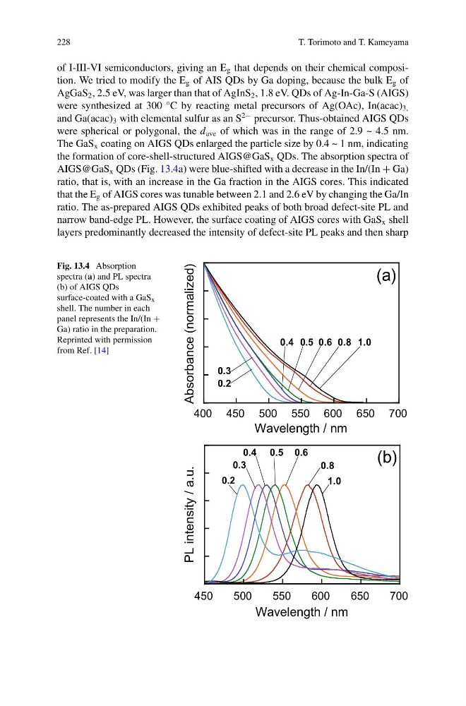
the formation of core-shell-structured AIGS@GaS x QDs. The absorption spectra of
AIGS@GaS x QDs (Fig. 13.4a) were blue-shifted with a decrease in the In/(In + Ga)
ratio, that is, with an increase in the Ga fraction in the AIGS cores. This indicated
that the E g of AIGS cores was tunable between 2.1 and 2.6 eV by changing the Ga/In
ratio. The as-prepared AIGS QDs exhibited peaks of both broad defect-site PL and
narrow band-edge PL. However, the surface coating of AIGS cores with GaS x shell
layers predominantly decreased the intensity of defect-site PL peaks and then sharp
Fig. 13.4 Absorption
spectra (a) and PL spectra
(b) of AIGS QDs
surface-coated with a GaS x
shell. The number in each
panel represents the In/(In +
Ga) ratio in the preparation.
Reprinted with permission
from Ref. [14]
450
500
550
600
650
700
PL intensity / a.u.
Wavelength / nm
0.3
0.4 0.5 0.6
0.8
1.0
0.2
(b)
Absorbance (normalized)
400 450 500 550 600 650 700
Wavelength / nm
0.3
0.4 0.5 0.6 0.8 1.0
(a)
0.2
T. Torimoto and T. Kameyama
of I-III-VI semiconductors, giving an E g that depends on their chemical composition. We tried to modify the E g of AIS QDs by Ga doping, because the bulk E g of
AgGaS 2 , 2.5 eV, was larger than that of AgInS 2 , 1.8 eV. QDs of Ag-In-Ga-S (AIGS)
were synthesized at 300 °C by reacting metal precursors of Ag(OAc), In(acac) 3,
and Ga(acac) 3 with elemental sulfur as an S
2− precursor. Thus-obtained AIGS QDs
were spherical or polygonal, the d ave of which was in the range of 2.9 ~ 4.5 nm.
The GaS x coating on AIGS QDs enlarged the particle size by 0.4 ~ 1 nm, indicating
the formation of core-shell-structured AIGS@GaS x QDs. The absorption spectra of
AIGS@GaS x QDs (Fig. 13.4a) were blue-shifted with a decrease in the In/(In + Ga)
ratio, that is, with an increase in the Ga fraction in the AIGS cores. This indicated
that the E g of AIGS cores was tunable between 2.1 and 2.6 eV by changing the Ga/In
ratio. The as-prepared AIGS QDs exhibited peaks of both broad defect-site PL and
narrow band-edge PL. However, the surface coating of AIGS cores with GaS x shell
layers predominantly decreased the intensity of defect-site PL peaks and then sharp
Fig. 13.4 Absorption
spectra (a) and PL spectra
(b) of AIGS QDs
surface-coated with a GaS x
shell. The number in each
panel represents the In/(In +
Ga) ratio in the preparation.
Reprinted with permission
from Ref. [14]
450
500
550
600
650
700
PL intensity / a.u.
Wavelength / nm
0.3
0.4 0.5 0.6
0.8
1.0
0.2
(b)
Absorbance (normalized)
400 450 500 550 600 650 700
Wavelength / nm
0.3
0.4 0.5 0.6 0.8 1.0
(a)
0.2