

Feedstocks
“biomass”
Crops
Agricultural
residues
Cellulosic
sludges
Waste
paper
Wood
Starch
Molasses
The
Biofine
process
Levulinic
acid
Formic
acid
Furfural
Ligneous
char
Products
Specialty
chemicals
Commodity
chemicals
Downstream
Herbicides
conversion
Pesticides
Heating oil
Transportation
fuels
Sucrose +
xylose
H 2
Hydrogenation
Ru/carbon
Aqueous-phase
reforming
Pt+Re/carbon
(a)
Carbon (%)
LHV (%)
Feeds
Tungstated
zirconia
Sucrose +
xylose
Hydrogen
100
–
12
87
Products
CO 2
25
–
ZSM-5
H 2
–
3
C 1 –C 4
26
31
C 5 –C 9
43
53
C 10+
5
6
(b)
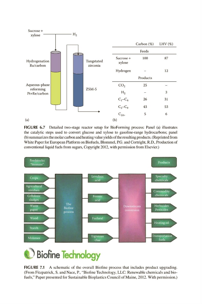
FIGURE 6.7 Detailed two-stage reactor setup for BioForming process: Panel (a) illustrates
the catalytic steps used to convert glucose and xylose to gasoline-range hydrocarbons; panel
(b) s ummarizes the molar carbon and heating value yields of the resulting products. (Reprinted from
White Paper for European Platform on Biofuels, Blommel, P.G. and Cortright, R.D., Production of
conventional liquid fuels from sugars, Copyright 2012, with permission from Elsevier.)
FIGURE 7.1 A schematic of the overall Biofine process that includes product upgrading.
(From Fitzpatrick, S. and Nace, P., “Biofine Technology, LLC: Renewable chemicals and biofuels,” Paper presented for Sustainable Bioplastics Council of Maine, 2012. With permission.)
“biomass”
Crops
Agricultural
residues
Cellulosic
sludges
Waste
paper
Wood
Starch
Molasses
The
Biofine
process
Levulinic
acid
Formic
acid
Furfural
Ligneous
char
Products
Specialty
chemicals
Commodity
chemicals
Downstream
Herbicides
conversion
Pesticides
Heating oil
Transportation
fuels
Sucrose +
xylose
H 2
Hydrogenation
Ru/carbon
Aqueous-phase
reforming
Pt+Re/carbon
(a)
Carbon (%)
LHV (%)
Feeds
Tungstated
zirconia
Sucrose +
xylose
Hydrogen
100
–
12
87
Products
CO 2
25
–
ZSM-5
H 2
–
3
C 1 –C 4
26
31
C 5 –C 9
43
53
C 10+
5
6
(b)
FIGURE 6.7 Detailed two-stage reactor setup for BioForming process: Panel (a) illustrates
the catalytic steps used to convert glucose and xylose to gasoline-range hydrocarbons; panel
(b) s ummarizes the molar carbon and heating value yields of the resulting products. (Reprinted from
White Paper for European Platform on Biofuels, Blommel, P.G. and Cortright, R.D., Production of
conventional liquid fuels from sugars, Copyright 2012, with permission from Elsevier.)
FIGURE 7.1 A schematic of the overall Biofine process that includes product upgrading.
(From Fitzpatrick, S. and Nace, P., “Biofine Technology, LLC: Renewable chemicals and biofuels,” Paper presented for Sustainable Bioplastics Council of Maine, 2012. With permission.)