

3.6 Methods
71
Temperature
controller
Water
heating
system
Water pump
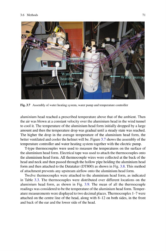
Fig. 3.7 Assembly of water heating system, water pump and temperature controller
aluminium head reached a prescribed temperature above that of the ambient. Then
the air was blown at a constant velocity over the aluminium head in the wind tunnel
to cool it. The temperature of the aluminium head form initially dropped by a large
amount and then the temperature drop was gradual until a steady state was reached.
The higher the drop in the average temperature of the aluminium head form, the
better ventilated and cooler the helmet will be. Figure 3.7 shows the assembly of the
temperature controller and water heating system together with the electric pump.
T-type thermocouples were used to measure the temperatures on the surface of
the aluminium head form. Electrical tape was used to attach the thermocouples onto
the aluminium head form. All thermocouple wires were collected at the back of the
head and neck and then passed through the hollow pipe holding the aluminium head
form and then attached to the Datataker (DT800) as shown in Fig. 3.8. This method
of attachment prevents any upstream airflow onto the aluminium head form.
Twelve thermocouples were attached to the aluminium head form, as indicated
in Table 3.3. The thermocouples were distributed over different locations on the
aluminium head form, as shown in Fig. 3.9. The mean of all the thermocouple
readings was considered to be the temperature of the aluminium head form. Temperature measurements were displayed to two decimal places. Thermocouples 1–7 were
attached on the centre line of the head, along with 8–12 on both sides, in the front
and back of the ear and the lower side of the head.
71
Temperature
controller
Water
heating
system
Water pump
Fig. 3.7 Assembly of water heating system, water pump and temperature controller
aluminium head reached a prescribed temperature above that of the ambient. Then
the air was blown at a constant velocity over the aluminium head in the wind tunnel
to cool it. The temperature of the aluminium head form initially dropped by a large
amount and then the temperature drop was gradual until a steady state was reached.
The higher the drop in the average temperature of the aluminium head form, the
better ventilated and cooler the helmet will be. Figure 3.7 shows the assembly of the
temperature controller and water heating system together with the electric pump.
T-type thermocouples were used to measure the temperatures on the surface of
the aluminium head form. Electrical tape was used to attach the thermocouples onto
the aluminium head form. All thermocouple wires were collected at the back of the
head and neck and then passed through the hollow pipe holding the aluminium head
form and then attached to the Datataker (DT800) as shown in Fig. 3.8. This method
of attachment prevents any upstream airflow onto the aluminium head form.
Twelve thermocouples were attached to the aluminium head form, as indicated
in Table 3.3. The thermocouples were distributed over different locations on the
aluminium head form, as shown in Fig. 3.9. The mean of all the thermocouple
readings was considered to be the temperature of the aluminium head form. Temperature measurements were displayed to two decimal places. Thermocouples 1–7 were
attached on the centre line of the head, along with 8–12 on both sides, in the front
and back of the ear and the lower side of the head.