

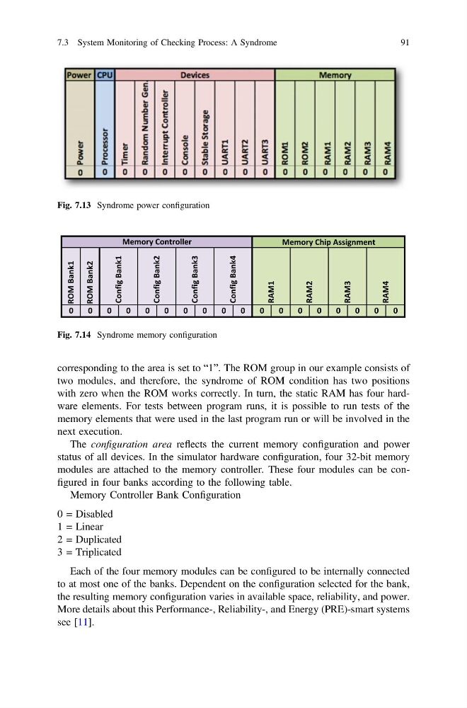
corresponding to the area is set to “1”. The ROM group in our example consists of
two modules, and therefore, the syndrome of ROM condition has two positions
with zero when the ROM works correctly. In turn, the static RAM has four hardware elements. For tests between program runs, it is possible to run tests of the
memory elements that were used in the last program run or will be involved in the
next execution.
The configuration area reflects the current memory configuration and power
status of all devices. In the simulator hardware configuration, four 32-bit memory
modules are attached to the memory controller. These four modules can be configured in four banks according to the following table.
Memory Controller Bank Configuration
0 = Disabled
1 = Linear
2 = Duplicated
3 = Triplicated
Each of the four memory modules can be configured to be internally connected
to at most one of the banks. Dependent on the configuration selected for the bank,
the resulting memory configuration varies in available space, reliability, and power.
More details about this Performance-, Reliability-, and Energy (PRE)-smart systems
see [11].
Fig. 7.13 Syndrome power configuration
Fig. 7.14 Syndrome memory configuration
7.3 System Monitoring of Checking Process: A Syndrome
91
two modules, and therefore, the syndrome of ROM condition has two positions
with zero when the ROM works correctly. In turn, the static RAM has four hardware elements. For tests between program runs, it is possible to run tests of the
memory elements that were used in the last program run or will be involved in the
next execution.
The configuration area reflects the current memory configuration and power
status of all devices. In the simulator hardware configuration, four 32-bit memory
modules are attached to the memory controller. These four modules can be configured in four banks according to the following table.
Memory Controller Bank Configuration
0 = Disabled
1 = Linear
2 = Duplicated
3 = Triplicated
Each of the four memory modules can be configured to be internally connected
to at most one of the banks. Dependent on the configuration selected for the bank,
the resulting memory configuration varies in available space, reliability, and power.
More details about this Performance-, Reliability-, and Energy (PRE)-smart systems
see [11].
Fig. 7.13 Syndrome power configuration
Fig. 7.14 Syndrome memory configuration
7.3 System Monitoring of Checking Process: A Syndrome
91