

47
3
3.2 · Reactions at the Carboxy Group of Fatty Acids
compressed hydrogen (compressor P2, 200–
300 bar). The heat exchanger H1 and the heater
H2 carry out heating to reaction temperature
(200–250 °C). After the reaction, the product
stream gives part of its energy to the input flow
(“feed”) and is further cooled in the cooler H3.
The reaction is carried out with a large excess of
hydrogen in order to achieve almost 100% conversion of the fatty ester. To separate the excess
gaseous hydrogen from the liquid product
stream, a separator S and a cyclone C are connected in series. The excess hydrogen is recycled,
while the liquid stream is expanded in a flash
with valve V and separated into gaseous methanol and liquid crude fatty alcohols.
The composition of the heterogeneous catalysts in reactor R can vary. Catalysts made from
copper oxide and chromium oxide are often
used. Palladium/rhenium and rhodium/tin catalysts have also been patented for this reaction.
These catalysts hydrogenate both the carboxyl
group to the alcohol group and the C=C double
bonds in the chain. If zinc is added during the
BOX: Fatty Alcohols - A Retroperspective and a Look at the Competitors
Historically, the conversion of
fatty esters to fatty alcohols
on a technical scale was first
carried out (since 1903) using
the Bouveault–Blanc process by
reduction with liquid metallic
sodium. In 1931, Deutsche
Hydrierwerke AG (Dehydag)
built the first catalytic ester
hydrogenation plant in
Rodleben/Germany. This ester
hydrogenation is still in strong
competition with two synthetic
processes for the production of
long-chain alcohols, which are
also known as “fatty alcohols”,
although they are based on
petrochemicals. These two
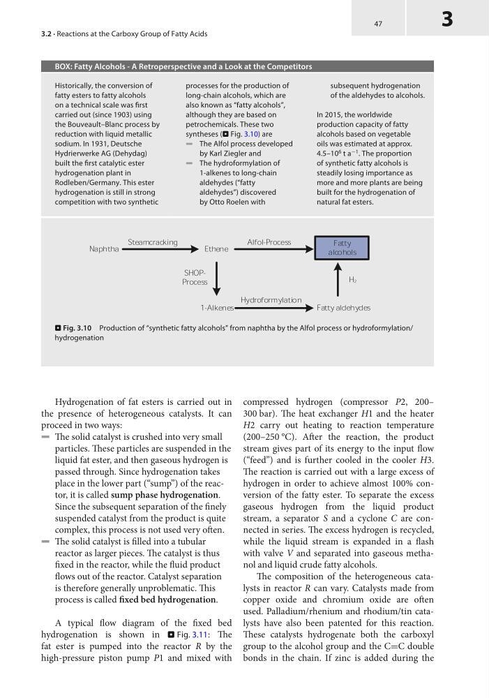
syntheses (. Fig. 3.10) are
5 The Alfol process developed
by Karl Ziegler and
5 The hydroformylation of
1-alkenes to long-chain
aldehydes (“fatty
aldehydes”) discovered
by Otto Roelen with
subsequent hydrogenation
of the aldehydes to alcohols.
In 2015, the worldwide
production capacity of fatty
alcohols based on vegetable
oils was estimated at approx.
4.5–10 6 t a −1 . The proportion
of synthetic fatty alcohols is
steadily losing importance as
more and more plants are being
built for the hydrogenation of
natural fat esters.
. Fig. 3.10 Production of “synthetic fatty alcohols” from naphtha by the Alfol process or hydroformylation/
hydrogenation
Hydrogenation of fat esters is carried out in
the presence of heterogeneous catalysts. It can
proceed in two ways:
5 The solid catalyst is crushed into very small
particles. These particles are suspended in the
liquid fat ester, and then gaseous hydrogen is
passed through. Since hydrogenation takes
place in the lower part (“sump”) of the reactor, it is called sump phase hydrogenation.
Since the subsequent separation of the finely
suspended catalyst from the product is quite
complex, this process is not used very often.
5 The solid catalyst is filled into a tubular
reactor as larger pieces. The catalyst is thus
fixed in the reactor, while the fluid product
flows out of the reactor. Catalyst separation
is therefore generally unproblematic. This
process is called fixed bed hydrogenation.
A typical flow diagram of the fixed bed
hydrogenation is shown in . Fig. 3.11: The
fat ester is pumped into the reactor R by the
high-pressure piston pump P1 and mixed with
3
3.2 · Reactions at the Carboxy Group of Fatty Acids
compressed hydrogen (compressor P2, 200–
300 bar). The heat exchanger H1 and the heater
H2 carry out heating to reaction temperature
(200–250 °C). After the reaction, the product
stream gives part of its energy to the input flow
(“feed”) and is further cooled in the cooler H3.
The reaction is carried out with a large excess of
hydrogen in order to achieve almost 100% conversion of the fatty ester. To separate the excess
gaseous hydrogen from the liquid product
stream, a separator S and a cyclone C are connected in series. The excess hydrogen is recycled,
while the liquid stream is expanded in a flash
with valve V and separated into gaseous methanol and liquid crude fatty alcohols.
The composition of the heterogeneous catalysts in reactor R can vary. Catalysts made from
copper oxide and chromium oxide are often
used. Palladium/rhenium and rhodium/tin catalysts have also been patented for this reaction.
These catalysts hydrogenate both the carboxyl
group to the alcohol group and the C=C double
bonds in the chain. If zinc is added during the
BOX: Fatty Alcohols - A Retroperspective and a Look at the Competitors
Historically, the conversion of
fatty esters to fatty alcohols
on a technical scale was first
carried out (since 1903) using
the Bouveault–Blanc process by
reduction with liquid metallic
sodium. In 1931, Deutsche
Hydrierwerke AG (Dehydag)
built the first catalytic ester
hydrogenation plant in
Rodleben/Germany. This ester
hydrogenation is still in strong
competition with two synthetic
processes for the production of
long-chain alcohols, which are
also known as “fatty alcohols”,
although they are based on
petrochemicals. These two
syntheses (. Fig. 3.10) are
5 The Alfol process developed
by Karl Ziegler and
5 The hydroformylation of
1-alkenes to long-chain
aldehydes (“fatty
aldehydes”) discovered
by Otto Roelen with
subsequent hydrogenation
of the aldehydes to alcohols.
In 2015, the worldwide
production capacity of fatty
alcohols based on vegetable
oils was estimated at approx.
4.5–10 6 t a −1 . The proportion
of synthetic fatty alcohols is
steadily losing importance as
more and more plants are being
built for the hydrogenation of
natural fat esters.
. Fig. 3.10 Production of “synthetic fatty alcohols” from naphtha by the Alfol process or hydroformylation/
hydrogenation
Hydrogenation of fat esters is carried out in
the presence of heterogeneous catalysts. It can
proceed in two ways:
5 The solid catalyst is crushed into very small
particles. These particles are suspended in the
liquid fat ester, and then gaseous hydrogen is
passed through. Since hydrogenation takes
place in the lower part (“sump”) of the reactor, it is called sump phase hydrogenation.
Since the subsequent separation of the finely
suspended catalyst from the product is quite
complex, this process is not used very often.
5 The solid catalyst is filled into a tubular
reactor as larger pieces. The catalyst is thus
fixed in the reactor, while the fluid product
flows out of the reactor. Catalyst separation
is therefore generally unproblematic. This
process is called fixed bed hydrogenation.
A typical flow diagram of the fixed bed
hydrogenation is shown in . Fig. 3.11: The
fat ester is pumped into the reactor R by the
high-pressure piston pump P1 and mixed with