

(3) Hydraulic Components
Develop large capacity hydraulic components, such as three-stage
electro-hydraulic servo valve. The three-stage electro-hydraulic servo valve
for Saturn-V rocket has a spool diameter of 25:4 mm, a stroke of Æ2:79 mm,
and a flow rate of 510 L=min
ð
Þ. A dynamic pressure feedback electro-hydraulic
servo valve was developed and applied for swing nozzle of high-power rocket
engine (its mass is 4000*8000 kg). It can realize dynamic damping to control
the movement of a large inertia load, restrain the resonance of the system, and
ensure a wider passband.
(4) Manufacturing Technology
The processing requirements of large parts in high-power system are high, and
technologies such as centrifugal casting, heat treatment, precision processing of
inner holes, surface treatment, static pressure strength, and sealing test should be
solved. Actuator barrels (16 pairs) of hydraulic load-bearing platform of giant
rocket erecting transporter have a maximum size of 680 Â 534 Â 2540 ðmmÞ
(inner diameter  outer diameter  length). The static load of the actuator
barrel (single piece) loading test is 22701 t, and the pressure of the oil chamber
does not decrease within 24 h, and the position of the piston does not drift.
9.1.3.2 High Pressure and High Temperature
(1) High Pressure
From the 1940s to the present, the common working pressure of hydraulic
system has increased from 5 to 27:4 MPa. In the 1980s, the United States
developed a 55 MPa working pressure hydraulic system for F-14 fighter aircraft
and replaced the original 20:6 MPa working pressure. The whole-system
ground simulation test and single-channel flight test were completed. The
prototype operated for 520 h. When the working pressure of the system is
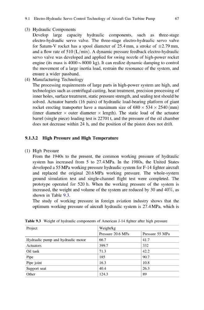
increased, the weight and volume of the system are reduced by 30 and 40%, as
shown in Table 9.3.
The study of working pressure in foreign aviation industry shows that the
optimum working pressure of aircraft hydraulic system is 27:4 MPa, which is
Table 9.3 Weight of hydraulic components of American J-14 fighter after high pressure
Project
Weight/kg
Pressure 20.6 MPa
Pressure 55 MPa
Hydraulic pump and hydraulic motor
66.7
41.7
Actuators
399.7
332
Oil tank
71.3
42.2
Pipe
185
90.7
Pipe joint
16.3
10.8
Support seat
40.4
26.3
Other
124.3
89
9.1 Electro-Hydraulic Servo Control Technology of Aircraft Gas Turbine Pump
67
Develop large capacity hydraulic components, such as three-stage
electro-hydraulic servo valve. The three-stage electro-hydraulic servo valve
for Saturn-V rocket has a spool diameter of 25:4 mm, a stroke of Æ2:79 mm,
and a flow rate of 510 L=min
ð
Þ. A dynamic pressure feedback electro-hydraulic
servo valve was developed and applied for swing nozzle of high-power rocket
engine (its mass is 4000*8000 kg). It can realize dynamic damping to control
the movement of a large inertia load, restrain the resonance of the system, and
ensure a wider passband.
(4) Manufacturing Technology
The processing requirements of large parts in high-power system are high, and
technologies such as centrifugal casting, heat treatment, precision processing of
inner holes, surface treatment, static pressure strength, and sealing test should be
solved. Actuator barrels (16 pairs) of hydraulic load-bearing platform of giant
rocket erecting transporter have a maximum size of 680 Â 534 Â 2540 ðmmÞ
(inner diameter  outer diameter  length). The static load of the actuator
barrel (single piece) loading test is 22701 t, and the pressure of the oil chamber
does not decrease within 24 h, and the position of the piston does not drift.
9.1.3.2 High Pressure and High Temperature
(1) High Pressure
From the 1940s to the present, the common working pressure of hydraulic
system has increased from 5 to 27:4 MPa. In the 1980s, the United States
developed a 55 MPa working pressure hydraulic system for F-14 fighter aircraft
and replaced the original 20:6 MPa working pressure. The whole-system
ground simulation test and single-channel flight test were completed. The
prototype operated for 520 h. When the working pressure of the system is
increased, the weight and volume of the system are reduced by 30 and 40%, as
shown in Table 9.3.
The study of working pressure in foreign aviation industry shows that the
optimum working pressure of aircraft hydraulic system is 27:4 MPa, which is
Table 9.3 Weight of hydraulic components of American J-14 fighter after high pressure
Project
Weight/kg
Pressure 20.6 MPa
Pressure 55 MPa
Hydraulic pump and hydraulic motor
66.7
41.7
Actuators
399.7
332
Oil tank
71.3
42.2
Pipe
185
90.7
Pipe joint
16.3
10.8
Support seat
40.4
26.3
Other
124.3
89
9.1 Electro-Hydraulic Servo Control Technology of Aircraft Gas Turbine Pump
67