

In addition, V 1 À V 2 is the maximum volume of accumulator when the maximum working pressure is applied, and V 3 À V 2 is the working supply volume of
accumulator.
The maximum oil filling capacity of hydraulic accumulator can be obtained from
Eqs. (8.55) and (8.56).
V a ¼ V 1 À V 2 ¼ V 1 1 À
p 1
p 2
1
n
"
#
ð8:57Þ
The working oil supply volume of hydraulic accumulator is
V b ¼ V 3 À V 2 ¼ V 1
p 1
p 2
1
n
p 2
p 3
1
n À1
"
#
ð8:58Þ
In order to reduce the mass and volume of aircraft, the volume of fuel tank in
hydraulic system can be designed as minimum as possible if it satisfies the change
of oil volume during flight. The maximum volume of oil entering the hydraulic
accumulator from the system, i.e., the maximum oil filling capacity of the accumulator, is an important index for the design of the hydraulic accumulator, booster
tank, and closed hydraulic system of the aircraft, which must be fully considered.
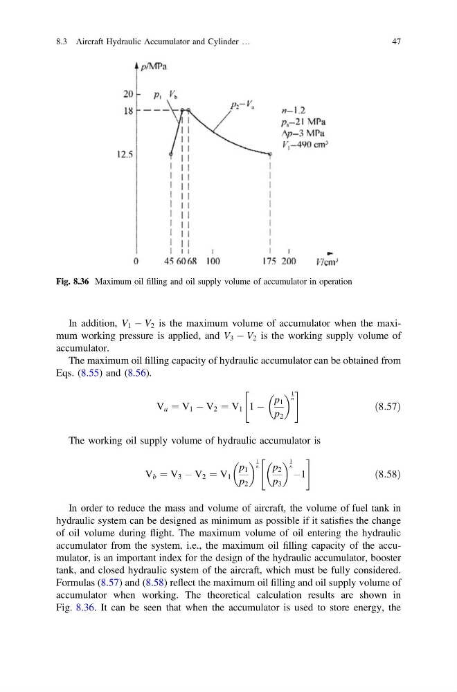
Formulas (8.57) and (8.58) reflect the maximum oil filling and oil supply volume of
accumulator when working. The theoretical calculation results are shown in
Fig. 8.36. It can be seen that when the accumulator is used to store energy, the
Fig. 8.36 Maximum oil filling and oil supply volume of accumulator in operation
8.3 Aircraft Hydraulic Accumulator and Cylinder …
47
accumulator.
The maximum oil filling capacity of hydraulic accumulator can be obtained from
Eqs. (8.55) and (8.56).
V a ¼ V 1 À V 2 ¼ V 1 1 À
p 1
p 2
1
n
"
#
ð8:57Þ
The working oil supply volume of hydraulic accumulator is
V b ¼ V 3 À V 2 ¼ V 1
p 1
p 2
1
n
p 2
p 3
1
n À1
"
#
ð8:58Þ
In order to reduce the mass and volume of aircraft, the volume of fuel tank in
hydraulic system can be designed as minimum as possible if it satisfies the change
of oil volume during flight. The maximum volume of oil entering the hydraulic
accumulator from the system, i.e., the maximum oil filling capacity of the accumulator, is an important index for the design of the hydraulic accumulator, booster
tank, and closed hydraulic system of the aircraft, which must be fully considered.
Formulas (8.57) and (8.58) reflect the maximum oil filling and oil supply volume of
accumulator when working. The theoretical calculation results are shown in
Fig. 8.36. It can be seen that when the accumulator is used to store energy, the
Fig. 8.36 Maximum oil filling and oil supply volume of accumulator in operation
8.3 Aircraft Hydraulic Accumulator and Cylinder …
47