

helium as a working medium. At present, however, the cost of helium production is
relatively high.
8.3.5 Service Characteristics of Accumulator
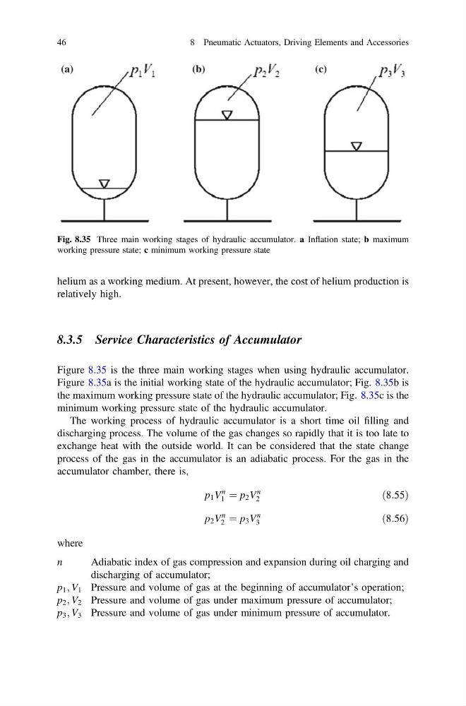
Figure 8.35 is the three main working stages when using hydraulic accumulator.
Figure 8.35a is the initial working state of the hydraulic accumulator; Fig. 8.35b is
the maximum working pressure state of the hydraulic accumulator; Fig. 8.35c is the
minimum working pressure state of the hydraulic accumulator.
The working process of hydraulic accumulator is a short time oil filling and
discharging process. The volume of the gas changes so rapidly that it is too late to
exchange heat with the outside world. It can be considered that the state change
process of the gas in the accumulator is an adiabatic process. For the gas in the
accumulator chamber, there is,
p 1 V
n
1 ¼ p 2 V
n
2
ð8:55Þ
p 2 V
n
2 ¼ p 3 V
n
3
ð8:56Þ
where
n
Adiabatic index of gas compression and expansion during oil charging and
discharging of accumulator;
p 1 ; V 1 Pressure and volume of gas at the beginning of accumulator’s operation;
p 2 ; V 2 Pressure and volume of gas under maximum pressure of accumulator;
p 3 ; V 3 Pressure and volume of gas under minimum pressure of accumulator.
Fig. 8.35 Three main working stages of hydraulic accumulator. a Inflation state; b maximum
working pressure state; c minimum working pressure state
46
8 Pneumatic Actuators, Driving Elements and Accessories
relatively high.
8.3.5 Service Characteristics of Accumulator
Figure 8.35 is the three main working stages when using hydraulic accumulator.
Figure 8.35a is the initial working state of the hydraulic accumulator; Fig. 8.35b is
the maximum working pressure state of the hydraulic accumulator; Fig. 8.35c is the
minimum working pressure state of the hydraulic accumulator.
The working process of hydraulic accumulator is a short time oil filling and
discharging process. The volume of the gas changes so rapidly that it is too late to
exchange heat with the outside world. It can be considered that the state change
process of the gas in the accumulator is an adiabatic process. For the gas in the
accumulator chamber, there is,
p 1 V
n
1 ¼ p 2 V
n
2
ð8:55Þ
p 2 V
n
2 ¼ p 3 V
n
3
ð8:56Þ
where
n
Adiabatic index of gas compression and expansion during oil charging and
discharging of accumulator;
p 1 ; V 1 Pressure and volume of gas at the beginning of accumulator’s operation;
p 2 ; V 2 Pressure and volume of gas under maximum pressure of accumulator;
p 3 ; V 3 Pressure and volume of gas under minimum pressure of accumulator.
Fig. 8.35 Three main working stages of hydraulic accumulator. a Inflation state; b maximum
working pressure state; c minimum working pressure state
46
8 Pneumatic Actuators, Driving Elements and Accessories