

p ¼
mR
M V À m=M
ð
Þb
½
T À
m
2
M 2
a
V 2
ð8:54Þ
Equation (8.54) reflects the variation of pressure of a certain mass gas with
temperature. It can be seen that the gas pressure has a linear relationship with the
absolute temperature of the gas, and also with the molar number of gas m=M, gas
constant a, b. The smaller the molar number of gas m=M, the larger the gas constant
b, the smaller the slope of pressure–temperature curve is shown in Eq. (8.54), and
the more stable the pressure changes with temperature.
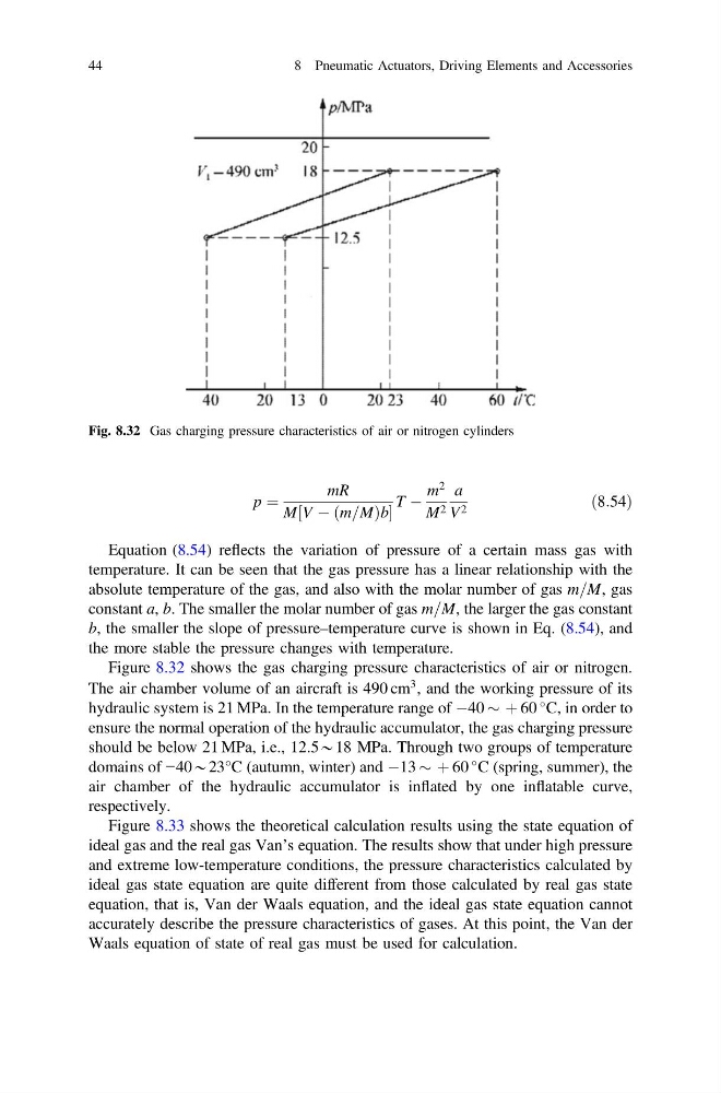
Figure 8.32 shows the gas charging pressure characteristics of air or nitrogen.
The air chamber volume of an aircraft is 490 cm
3 , and the working pressure of its
hydraulic system is 21 MPa. In the temperature range of À40 $ þ 60
C, in order to
ensure the normal operation of the hydraulic accumulator, the gas charging pressure
should be below 21 MPa, i.e., 12.5*18 MPa. Through two groups of temperature
domains of −40*23°C (autumn, winter) and À13 $ þ 60
C (spring, summer), the
air chamber of the hydraulic accumulator is inflated by one inflatable curve,
respectively.
Figure 8.33 shows the theoretical calculation results using the state equation of
ideal gas and the real gas Van’s equation. The results show that under high pressure
and extreme low-temperature conditions, the pressure characteristics calculated by
ideal gas state equation are quite different from those calculated by real gas state
equation, that is, Van der Waals equation, and the ideal gas state equation cannot
accurately describe the pressure characteristics of gases. At this point, the Van der
Waals equation of state of real gas must be used for calculation.
Fig. 8.32 Gas charging pressure characteristics of air or nitrogen cylinders
44
8 Pneumatic Actuators, Driving Elements and Accessories
mR
M V À m=M
ð
Þb
½
T À
m
2
M 2
a
V 2
ð8:54Þ
Equation (8.54) reflects the variation of pressure of a certain mass gas with
temperature. It can be seen that the gas pressure has a linear relationship with the
absolute temperature of the gas, and also with the molar number of gas m=M, gas
constant a, b. The smaller the molar number of gas m=M, the larger the gas constant
b, the smaller the slope of pressure–temperature curve is shown in Eq. (8.54), and
the more stable the pressure changes with temperature.
Figure 8.32 shows the gas charging pressure characteristics of air or nitrogen.
The air chamber volume of an aircraft is 490 cm
3 , and the working pressure of its
hydraulic system is 21 MPa. In the temperature range of À40 $ þ 60
C, in order to
ensure the normal operation of the hydraulic accumulator, the gas charging pressure
should be below 21 MPa, i.e., 12.5*18 MPa. Through two groups of temperature
domains of −40*23°C (autumn, winter) and À13 $ þ 60
C (spring, summer), the
air chamber of the hydraulic accumulator is inflated by one inflatable curve,
respectively.
Figure 8.33 shows the theoretical calculation results using the state equation of
ideal gas and the real gas Van’s equation. The results show that under high pressure
and extreme low-temperature conditions, the pressure characteristics calculated by
ideal gas state equation are quite different from those calculated by real gas state
equation, that is, Van der Waals equation, and the ideal gas state equation cannot
accurately describe the pressure characteristics of gases. At this point, the Van der
Waals equation of state of real gas must be used for calculation.
Fig. 8.32 Gas charging pressure characteristics of air or nitrogen cylinders
44
8 Pneumatic Actuators, Driving Elements and Accessories