

(1) Bidirectional nozzle
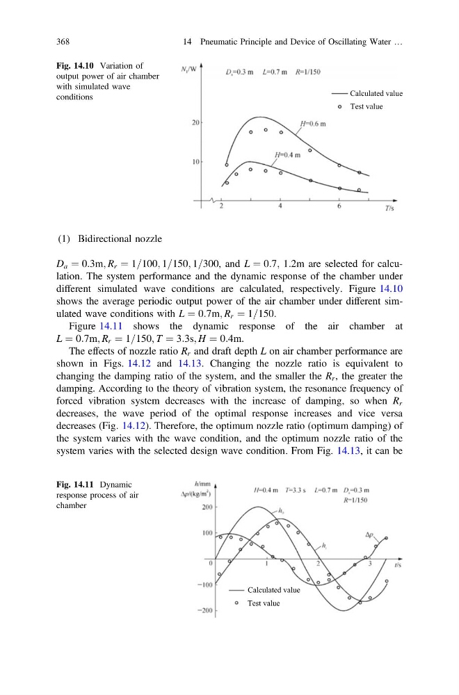
D a ¼ 0:3m; R r ¼ 1=100; 1=150; 1=300, and L ¼ 0:7; 1:2m are selected for calculation. The system performance and the dynamic response of the chamber under
different simulated wave conditions are calculated, respectively. Figure 14.10
shows the average periodic output power of the air chamber under different simulated wave conditions with L ¼ 0:7m; R r ¼ 1=150.
Figure 14.11 shows the dynamic response of the air chamber at
L ¼ 0:7m; R r ¼ 1=150; T ¼ 3:3s; H ¼ 0:4m.
The effects of nozzle ratio R r and draft depth L on air chamber performance are
shown in Figs. 14.12 and 14.13. Changing the nozzle ratio is equivalent to
changing the damping ratio of the system, and the smaller the R r , the greater the
damping. According to the theory of vibration system, the resonance frequency of
forced vibration system decreases with the increase of damping, so when R r
decreases, the wave period of the optimal response increases and vice versa
decreases (Fig. 14.12). Therefore, the optimum nozzle ratio (optimum damping) of
the system varies with the wave condition, and the optimum nozzle ratio of the
system varies with the selected design wave condition. From Fig. 14.13, it can be
Calculated value
Test value
Fig. 14.10 Variation of
output power of air chamber
with simulated wave
conditions
Calculated value
Test value
Fig. 14.11 Dynamic
response process of air
chamber
368
14 Pneumatic Principle and Device of Oscillating Water …
D a ¼ 0:3m; R r ¼ 1=100; 1=150; 1=300, and L ¼ 0:7; 1:2m are selected for calculation. The system performance and the dynamic response of the chamber under
different simulated wave conditions are calculated, respectively. Figure 14.10
shows the average periodic output power of the air chamber under different simulated wave conditions with L ¼ 0:7m; R r ¼ 1=150.
Figure 14.11 shows the dynamic response of the air chamber at
L ¼ 0:7m; R r ¼ 1=150; T ¼ 3:3s; H ¼ 0:4m.
The effects of nozzle ratio R r and draft depth L on air chamber performance are
shown in Figs. 14.12 and 14.13. Changing the nozzle ratio is equivalent to
changing the damping ratio of the system, and the smaller the R r , the greater the
damping. According to the theory of vibration system, the resonance frequency of
forced vibration system decreases with the increase of damping, so when R r
decreases, the wave period of the optimal response increases and vice versa
decreases (Fig. 14.12). Therefore, the optimum nozzle ratio (optimum damping) of
the system varies with the wave condition, and the optimum nozzle ratio of the
system varies with the selected design wave condition. From Fig. 14.13, it can be
Calculated value
Test value
Fig. 14.10 Variation of
output power of air chamber
with simulated wave
conditions
Calculated value
Test value
Fig. 14.11 Dynamic
response process of air
chamber
368
14 Pneumatic Principle and Device of Oscillating Water …