

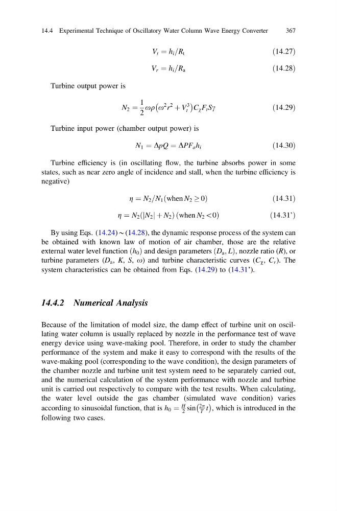
V t ¼ h i =R t
ð14:27Þ
V r ¼ h i =R a
ð14:28Þ
Turbine output power is
N 2 ¼
1
2
xq x
2 r
2
þ V
3
t
À
Á
C v F t Sc
ð14:29Þ
Turbine input power (chamber output power) is
N 1 ¼ DpQ ¼ DPF a h i
ð14:30Þ
Turbine efficiency is (in oscillating flow, the turbine absorbs power in some
states, such as near zero angle of incidence and stall, when the turbine efficiency is
negative)
g ¼ N 2 =N 1 when N 2 ! 0
ð
Þ
ð 14:31Þ
g ¼ N 2 N 2
j jþ N 2
ð
Þð when N 2 \0Þ
ð 14:31’Þ
By using Eqs. (14.24)*(14.28), the dynamic response process of the system can
be obtained with known law of motion of air chamber, those are the relative
external water level function h 0
ð Þ and design parameters D a ; L
ð
Þ, nozzle ratio (R), or
turbine parameters (D a , K, S, x) and turbine characteristic curves (C v , C r ). The
system characteristics can be obtained from Eqs. (14.29) to (14.31’).
14.4.2 Numerical Analysis
Because of the limitation of model size, the damp effect of turbine unit on oscillating water column is usually replaced by nozzle in the performance test of wave
energy device using wave-making pool. Therefore, in order to study the chamber
performance of the system and make it easy to correspond with the results of the
wave-making pool (corresponding to the wave condition), the design parameters of
the chamber nozzle and turbine unit test system need to be separately carried out,
and the numerical calculation of the system performance with nozzle and turbine
unit is carried out respectively to compare with the test results. When calculating,
the water level outside the gas chamber (simulated wave condition) varies
according to sinusoidal function, that is h 0 ¼
H
2 sin
2p
T t
À Á
, which is introduced in the
following two cases.
14.4 Experimental Technique of Oscillatory Water Column Wave Energy Converter
367
ð14:27Þ
V r ¼ h i =R a
ð14:28Þ
Turbine output power is
N 2 ¼
1
2
xq x
2 r
2
þ V
3
t
À
Á
C v F t Sc
ð14:29Þ
Turbine input power (chamber output power) is
N 1 ¼ DpQ ¼ DPF a h i
ð14:30Þ
Turbine efficiency is (in oscillating flow, the turbine absorbs power in some
states, such as near zero angle of incidence and stall, when the turbine efficiency is
negative)
g ¼ N 2 =N 1 when N 2 ! 0
ð
Þ
ð 14:31Þ
g ¼ N 2 N 2
j jþ N 2
ð
Þð when N 2 \0Þ
ð 14:31’Þ
By using Eqs. (14.24)*(14.28), the dynamic response process of the system can
be obtained with known law of motion of air chamber, those are the relative
external water level function h 0
ð Þ and design parameters D a ; L
ð
Þ, nozzle ratio (R), or
turbine parameters (D a , K, S, x) and turbine characteristic curves (C v , C r ). The
system characteristics can be obtained from Eqs. (14.29) to (14.31’).
14.4.2 Numerical Analysis
Because of the limitation of model size, the damp effect of turbine unit on oscillating water column is usually replaced by nozzle in the performance test of wave
energy device using wave-making pool. Therefore, in order to study the chamber
performance of the system and make it easy to correspond with the results of the
wave-making pool (corresponding to the wave condition), the design parameters of
the chamber nozzle and turbine unit test system need to be separately carried out,
and the numerical calculation of the system performance with nozzle and turbine
unit is carried out respectively to compare with the test results. When calculating,
the water level outside the gas chamber (simulated wave condition) varies
according to sinusoidal function, that is h 0 ¼
H
2 sin
2p
T t
À Á
, which is introduced in the
following two cases.
14.4 Experimental Technique of Oscillatory Water Column Wave Energy Converter
367