

value of l=k makes the water in the water tank resonate with the incident wave, so it
can achieve better results.
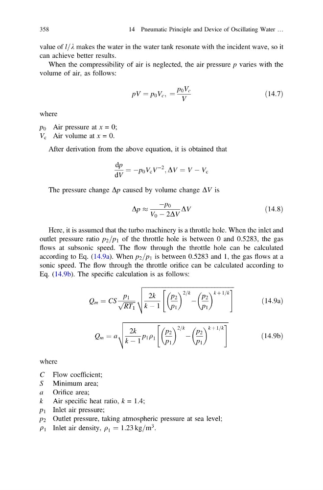
When the compressibility of air is neglected, the air pressure p varies with the
volume of air, as follows:
pV ¼ p 0 V c ; ¼
p 0 V c
V
ð14:7Þ
where
p 0 Air pressure at x = 0;
V c Air volume at x = 0.
After derivation from the above equation, it is obtained that
dp
dV
¼ Àp 0 V c V
À2
; DV ¼ V À V c
The pressure change Dp caused by volume change DV is
Dp %
Àp 0
V 0 À 2DV
DV
ð14:8Þ
Here, it is assumed that the turbo machinery is a throttle hole. When the inlet and
outlet pressure ratio p 2 =p 1 of the throttle hole is between 0 and 0.5283, the gas
flows at subsonic speed. The flow through the throttle hole can be calculated
according to Eq. (14.9a). When p 2 =p 1 is between 0.5283 and 1, the gas flows at a
sonic speed. The flow through the throttle orifice can be calculated according to
Eq. (14.9b). The specific calculation is as follows:
Q m ¼ CS
p 1
ffiffiffiffiffiffiffiffi
RT 1
p
ffiffiffiffiffiffiffiffiffiffiffiffiffiffiffiffiffiffiffiffiffiffiffiffiffiffiffiffiffiffiffiffiffiffiffiffiffiffiffiffiffiffiffiffiffiffiffiffiffiffiffiffiffiffiffiffiffiffiffi
2k
k À 1
p 2
p 1
2=k
À
p 2
p 1
k þ 1=k
"
#
v
u
u
t
ð14:9aÞ
Q m ¼ a
ffiffiffiffiffiffiffiffiffiffiffiffiffiffiffiffiffiffiffiffiffiffiffiffiffiffiffiffiffiffiffiffiffiffiffiffiffiffiffiffiffiffiffiffiffiffiffiffiffiffiffiffiffiffiffiffiffiffiffiffiffiffiffiffiffiffiffiffi
2k
k À 1
p 1 q 1
p 2
p 1
2=k
À
p 2
p 1
k þ 1=k
"
#
v
u
u
t
ð14:9bÞ
where
C Flow coefficient;
S Minimum area;
a Orifice area;
k Air specific heat ratio, k = 1.4;
p 1 Inlet air pressure;
p 2 Outlet pressure, taking atmospheric pressure at sea level;
q 1 Inlet air density, q 1 ¼ 1:23 kg=m
3 .
358
14 Pneumatic Principle and Device of Oscillating Water …
can achieve better results.
When the compressibility of air is neglected, the air pressure p varies with the
volume of air, as follows:
pV ¼ p 0 V c ; ¼
p 0 V c
V
ð14:7Þ
where
p 0 Air pressure at x = 0;
V c Air volume at x = 0.
After derivation from the above equation, it is obtained that
dp
dV
¼ Àp 0 V c V
À2
; DV ¼ V À V c
The pressure change Dp caused by volume change DV is
Dp %
Àp 0
V 0 À 2DV
DV
ð14:8Þ
Here, it is assumed that the turbo machinery is a throttle hole. When the inlet and
outlet pressure ratio p 2 =p 1 of the throttle hole is between 0 and 0.5283, the gas
flows at subsonic speed. The flow through the throttle hole can be calculated
according to Eq. (14.9a). When p 2 =p 1 is between 0.5283 and 1, the gas flows at a
sonic speed. The flow through the throttle orifice can be calculated according to
Eq. (14.9b). The specific calculation is as follows:
Q m ¼ CS
p 1
ffiffiffiffiffiffiffiffi
RT 1
p
ffiffiffiffiffiffiffiffiffiffiffiffiffiffiffiffiffiffiffiffiffiffiffiffiffiffiffiffiffiffiffiffiffiffiffiffiffiffiffiffiffiffiffiffiffiffiffiffiffiffiffiffiffiffiffiffiffiffiffi
2k
k À 1
p 2
p 1
2=k
À
p 2
p 1
k þ 1=k
"
#
v
u
u
t
ð14:9aÞ
Q m ¼ a
ffiffiffiffiffiffiffiffiffiffiffiffiffiffiffiffiffiffiffiffiffiffiffiffiffiffiffiffiffiffiffiffiffiffiffiffiffiffiffiffiffiffiffiffiffiffiffiffiffiffiffiffiffiffiffiffiffiffiffiffiffiffiffiffiffiffiffiffi
2k
k À 1
p 1 q 1
p 2
p 1
2=k
À
p 2
p 1
k þ 1=k
"
#
v
u
u
t
ð14:9bÞ
where
C Flow coefficient;
S Minimum area;
a Orifice area;
k Air specific heat ratio, k = 1.4;
p 1 Inlet air pressure;
p 2 Outlet pressure, taking atmospheric pressure at sea level;
q 1 Inlet air density, q 1 ¼ 1:23 kg=m
3 .
358
14 Pneumatic Principle and Device of Oscillating Water …