

12.5.2.2 Results
(1) Figures 12.32, 12.33 and 12.34 show the horizontal displacement contour map,
the vertical displacement contour map, and the total displacement contour map,
in unit of mm. From the displacement contour map, it can be seen that: As
shown in Fig. 12.32, in the horizontal displacement X-direction, the displacement field distribution diffuses outward in a layered form. The soil displacement near the pile tip is the smallest, and gradually increases with the distance
from the pile tip, but the displacement distribution area becomes smaller and
smaller. The maximum displacement is 96:96 mm and the minimum displacement is 10:85 mm. As shown in Fig. 12.33, in the Y-direction of vertical
displacement, the displacement of the pile body and the soil near the pile body
is the largest due to the downward impact load of the hammer body on the top
of the pile. The displacement at the top of the pile reaches 654:6 mm, and the
farther away from the pile, the smaller the displacement of the soil layer.
As shown in Fig. 12.34, the total displacement contour map is similar to the
Y-direction displacement distribution. The displacement of the pile body and
the area near the pile body is the largest. The farther away from the pile, the
smaller the displacement is. At a certain distance, the displacement is zero.
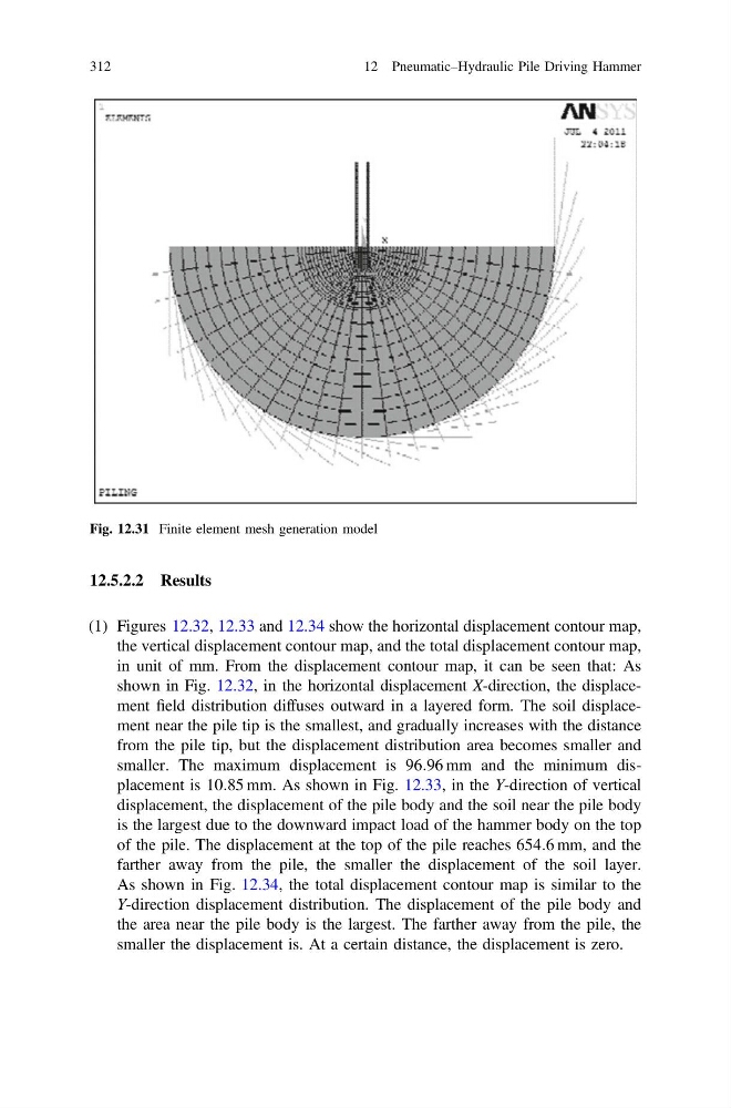
Fig. 12.31 Finite element mesh generation model
312
12 Pneumatic–Hydraulic Pile Driving Hammer
(1) Figures 12.32, 12.33 and 12.34 show the horizontal displacement contour map,
the vertical displacement contour map, and the total displacement contour map,
in unit of mm. From the displacement contour map, it can be seen that: As
shown in Fig. 12.32, in the horizontal displacement X-direction, the displacement field distribution diffuses outward in a layered form. The soil displacement near the pile tip is the smallest, and gradually increases with the distance
from the pile tip, but the displacement distribution area becomes smaller and
smaller. The maximum displacement is 96:96 mm and the minimum displacement is 10:85 mm. As shown in Fig. 12.33, in the Y-direction of vertical
displacement, the displacement of the pile body and the soil near the pile body
is the largest due to the downward impact load of the hammer body on the top
of the pile. The displacement at the top of the pile reaches 654:6 mm, and the
farther away from the pile, the smaller the displacement of the soil layer.
As shown in Fig. 12.34, the total displacement contour map is similar to the
Y-direction displacement distribution. The displacement of the pile body and
the area near the pile body is the largest. The farther away from the pile, the
smaller the displacement is. At a certain distance, the displacement is zero.
Fig. 12.31 Finite element mesh generation model
312
12 Pneumatic–Hydraulic Pile Driving Hammer