

Among them,
h r ¼ a tan
2r 2 À r 1 À r 3
ffiffi ffi
3
p r 1 À r 3
ð
Þ
!
ð12:58Þ
where
h r
Lode angle, which reflects material’s stress state parameters, ranges
À30
$ 30
;
r 1 ; r 2 ; r 3 First, second, and third principal stresses in principal stress space;
C
Soil material cohesion.
When h r ¼ À30
, the soil material is in the state of pure tension; when h r ¼ 0
,
the soil material is in the state of pure shear; when h r ¼ 30
, the soil material is in
the state of pure compression. In the process of Lode angle changing from À30
to
30
, the stress state of soil will change from tension type to compression type. Soil
Mohr–Coulomb (M-C) yield criterion can be regarded as a function of Lode angle
h r , while D-P yield criterion is M-C criterion when certain h r values are taken.
Therefore, according to the different values of h r , the position relationship between
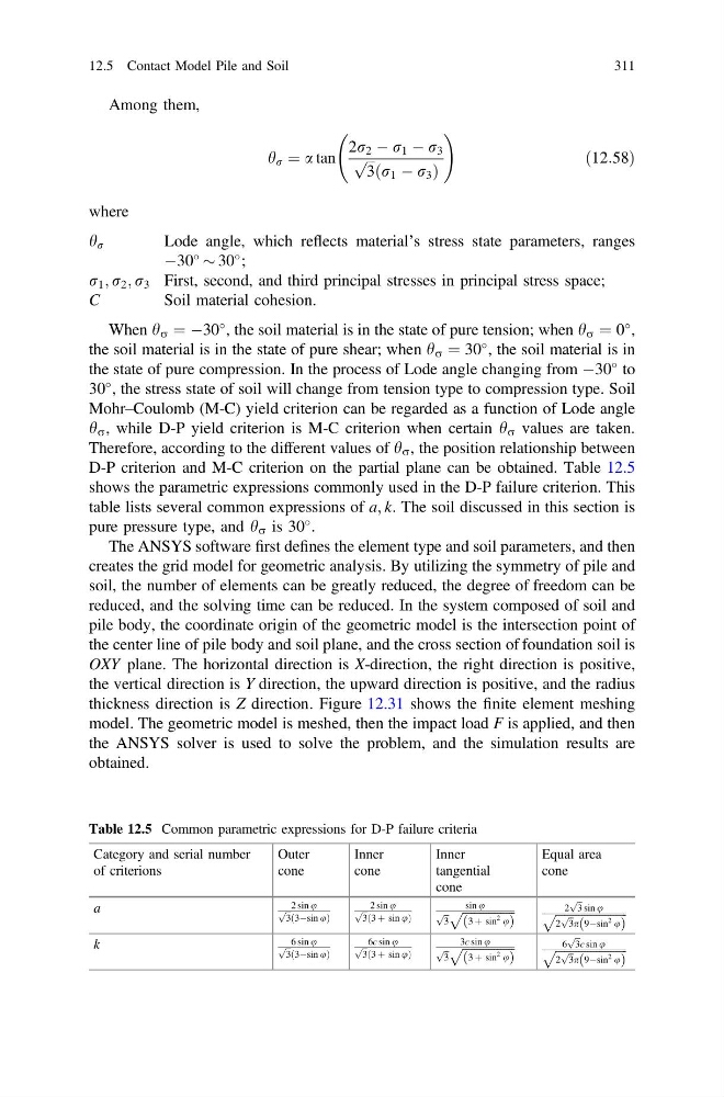
D-P criterion and M-C criterion on the partial plane can be obtained. Table 12.5
shows the parametric expressions commonly used in the D-P failure criterion. This
table lists several common expressions of a; k. The soil discussed in this section is
pure pressure type, and h r is 30
.
The ANSYS software first defines the element type and soil parameters, and then
creates the grid model for geometric analysis. By utilizing the symmetry of pile and
soil, the number of elements can be greatly reduced, the degree of freedom can be
reduced, and the solving time can be reduced. In the system composed of soil and
pile body, the coordinate origin of the geometric model is the intersection point of
the center line of pile body and soil plane, and the cross section of foundation soil is
OXY plane. The horizontal direction is X-direction, the right direction is positive,
the vertical direction is Y direction, the upward direction is positive, and the radius
thickness direction is Z direction. Figure 12.31 shows the finite element meshing
model. The geometric model is meshed, then the impact load F is applied, and then
the ANSYS solver is used to solve the problem, and the simulation results are
obtained.
Table 12.5 Common parametric expressions for D-P failure criteria
Category and serial number
of criterions
Outer
cone
Inner
cone
Inner
tangential
cone
Equal area
cone
a
2 sin u
ffiffi
3
p
3Àsin u
ð
Þ
2 sin u
ffiffi
3
p
3 þ sin u
ð
Þ
sin u
ffiffi
3
p
ffiffiffiffiffiffiffiffiffiffiffiffiffiffiffiffiffiffi
3 þ sin
2 u
ð
Þ
p
2
ffiffi
3
p
sin u
ffiffiffiffiffiffiffiffiffiffiffiffiffiffiffiffiffiffiffiffiffiffiffiffi ffi
2
ffiffi
3
p p 9Àsin
2 u
ð
Þ
p
k
6 sin u
ffiffi
3
p
3Àsin u
ð
Þ
6c sin u
ffiffi
3
p
3 þ sin u
ð
Þ
3c sin u
ffiffi
3
p
ffiffiffiffiffiffiffiffiffiffiffiffiffiffiffiffiffiffi
3 þ sin
2 u
ð
Þ
p
6
ffiffi
3
p
c sin u
ffiffiffiffiffiffiffiffiffiffiffiffiffiffiffiffiffiffiffiffiffiffiffiffi ffi
2
ffiffi
3
p p 9Àsin
2 u
ð
Þ
p
12.5 Contact Model Pile and Soil
311
h r ¼ a tan
2r 2 À r 1 À r 3
ffiffi ffi
3
p r 1 À r 3
ð
Þ
!
ð12:58Þ
where
h r
Lode angle, which reflects material’s stress state parameters, ranges
À30
$ 30
;
r 1 ; r 2 ; r 3 First, second, and third principal stresses in principal stress space;
C
Soil material cohesion.
When h r ¼ À30
, the soil material is in the state of pure tension; when h r ¼ 0
,
the soil material is in the state of pure shear; when h r ¼ 30
, the soil material is in
the state of pure compression. In the process of Lode angle changing from À30
to
30
, the stress state of soil will change from tension type to compression type. Soil
Mohr–Coulomb (M-C) yield criterion can be regarded as a function of Lode angle
h r , while D-P yield criterion is M-C criterion when certain h r values are taken.
Therefore, according to the different values of h r , the position relationship between
D-P criterion and M-C criterion on the partial plane can be obtained. Table 12.5
shows the parametric expressions commonly used in the D-P failure criterion. This
table lists several common expressions of a; k. The soil discussed in this section is
pure pressure type, and h r is 30
.
The ANSYS software first defines the element type and soil parameters, and then
creates the grid model for geometric analysis. By utilizing the symmetry of pile and
soil, the number of elements can be greatly reduced, the degree of freedom can be
reduced, and the solving time can be reduced. In the system composed of soil and
pile body, the coordinate origin of the geometric model is the intersection point of
the center line of pile body and soil plane, and the cross section of foundation soil is
OXY plane. The horizontal direction is X-direction, the right direction is positive,
the vertical direction is Y direction, the upward direction is positive, and the radius
thickness direction is Z direction. Figure 12.31 shows the finite element meshing
model. The geometric model is meshed, then the impact load F is applied, and then
the ANSYS solver is used to solve the problem, and the simulation results are
obtained.
Table 12.5 Common parametric expressions for D-P failure criteria
Category and serial number
of criterions
Outer
cone
Inner
cone
Inner
tangential
cone
Equal area
cone
a
2 sin u
ffiffi
3
p
3Àsin u
ð
Þ
2 sin u
ffiffi
3
p
3 þ sin u
ð
Þ
sin u
ffiffi
3
p
ffiffiffiffiffiffiffiffiffiffiffiffiffiffiffiffiffiffi
3 þ sin
2 u
ð
Þ
p
2
ffiffi
3
p
sin u
ffiffiffiffiffiffiffiffiffiffiffiffiffiffiffiffiffiffiffiffiffiffiffiffi ffi
2
ffiffi
3
p p 9Àsin
2 u
ð
Þ
p
k
6 sin u
ffiffi
3
p
3Àsin u
ð
Þ
6c sin u
ffiffi
3
p
3 þ sin u
ð
Þ
3c sin u
ffiffi
3
p
ffiffiffiffiffiffiffiffiffiffiffiffiffiffiffiffiffiffi
3 þ sin
2 u
ð
Þ
p
6
ffiffi
3
p
c sin u
ffiffiffiffiffiffiffiffiffiffiffiffiffiffiffiffiffiffiffiffiffiffiffiffi ffi
2
ffiffi
3
p p 9Àsin
2 u
ð
Þ
p
12.5 Contact Model Pile and Soil
311