

where
D Piston diameter;
d Piston rod diameter;
y r Rising displacement of hammer.
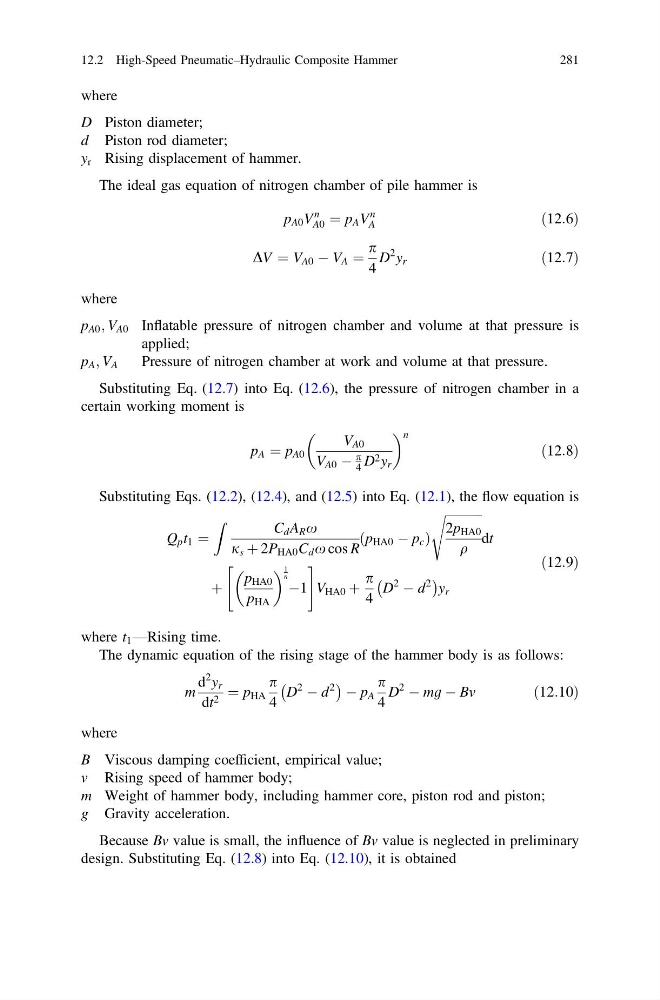
The ideal gas equation of nitrogen chamber of pile hammer is
p A0 V
n
A0 ¼ p A V
n
A
ð12:6Þ
DV ¼ V A0 À V A ¼
p
4
D
2 y r
ð12:7Þ
where
p A0 ; V A0 Inflatable pressure of nitrogen chamber and volume at that pressure is
applied;
p A ; V A
Pressure of nitrogen chamber at work and volume at that pressure.
Substituting Eq. (12.7) into Eq. (12.6), the pressure of nitrogen chamber in a
certain working moment is
p A ¼ p A0
V A0
V A0 À
p
4 D 2 y r
n
ð12:8Þ
Substituting Eqs. (12.2), (12.4), and (12.5) into Eq. (12.1), the flow equation is
Q p t 1 ¼
Z
C d A R x
j s þ 2P HA0 C d x cos R
p HA0 À p c
ð
Þ
ffiffiffiffiffiffiffiffiffiffiffiffi
2p HA0
q
s
dt
þ
p HA0
p HA
1
n À1
"
#
V HA0 þ
p
4
D
2
À d
2
À
Á
y r
ð12:9Þ
where t 1 —Rising time.
The dynamic equation of the rising stage of the hammer body is as follows:
m
d
2 y r
dt 2 ¼ p HA
p
4
D
2
À d
2
À
Á À p A
p
4
D
2
À mg À Bv
ð12:10Þ
where
B Viscous damping coefficient, empirical value;
v Rising speed of hammer body;
m Weight of hammer body, including hammer core, piston rod and piston;
g Gravity acceleration.
Because Bv value is small, the influence of Bv value is neglected in preliminary
design. Substituting Eq. (12.8) into Eq. (12.10), it is obtained
12.2 High-Speed Pneumatic–Hydraulic Composite Hammer
281
D Piston diameter;
d Piston rod diameter;
y r Rising displacement of hammer.
The ideal gas equation of nitrogen chamber of pile hammer is
p A0 V
n
A0 ¼ p A V
n
A
ð12:6Þ
DV ¼ V A0 À V A ¼
p
4
D
2 y r
ð12:7Þ
where
p A0 ; V A0 Inflatable pressure of nitrogen chamber and volume at that pressure is
applied;
p A ; V A
Pressure of nitrogen chamber at work and volume at that pressure.
Substituting Eq. (12.7) into Eq. (12.6), the pressure of nitrogen chamber in a
certain working moment is
p A ¼ p A0
V A0
V A0 À
p
4 D 2 y r
n
ð12:8Þ
Substituting Eqs. (12.2), (12.4), and (12.5) into Eq. (12.1), the flow equation is
Q p t 1 ¼
Z
C d A R x
j s þ 2P HA0 C d x cos R
p HA0 À p c
ð
Þ
ffiffiffiffiffiffiffiffiffiffiffiffi
2p HA0
q
s
dt
þ
p HA0
p HA
1
n À1
"
#
V HA0 þ
p
4
D
2
À d
2
À
Á
y r
ð12:9Þ
where t 1 —Rising time.
The dynamic equation of the rising stage of the hammer body is as follows:
m
d
2 y r
dt 2 ¼ p HA
p
4
D
2
À d
2
À
Á À p A
p
4
D
2
À mg À Bv
ð12:10Þ
where
B Viscous damping coefficient, empirical value;
v Rising speed of hammer body;
m Weight of hammer body, including hammer core, piston rod and piston;
g Gravity acceleration.
Because Bv value is small, the influence of Bv value is neglected in preliminary
design. Substituting Eq. (12.8) into Eq. (12.10), it is obtained
12.2 High-Speed Pneumatic–Hydraulic Composite Hammer
281