

Q A Flow rate provided by pump to high-pressure accumulator;
Q C Flow into rod chamber of hydraulic cylinder.
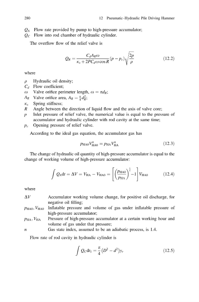
The overflow flow of the relief valve is
Q R ¼
C d A R x
j s þ 2PC d x cos R
p À p c
ð
Þ
ffiffiffiffiffi
2p
q
s
ð12:2Þ
where
q Hydraulic oil density;
C d Flow coefficient;
x Valve orifice perimeter length, x ¼ pd R ;
A R Valve orifice area, A R ¼
p
4 d
2
R ;
j s Spring stiffness;
R Angle between the direction of liquid flow and the axis of valve core;
p Inlet pressure of relief valve, the numerical value is equal to the pressure of
accumulator and hydraulic cylinder with rod cavity at the same time;
p c Opening pressure of relief valve.
According to the ideal gas equation, the accumulator gas has
p HA0 V
n
HA0 ¼ p HA V
n
HA
ð12:3Þ
The change of hydraulic oil quantity of high-pressure accumulator is equal to the
change of working volume of high-pressure accumulator:
Z
Q A dt ¼ DV ¼ V HA À V HA0 ¼
p HA0
p HA
1
n À1
"
#
V HA0
ð12:4Þ
where
DV
Accumulator working volume change, for positive oil discharge, for
negative oil filling;
p HA0 ; V HA0 Inflatable pressure and volume of gas under inflatable pressure of
high-pressure accumulator;
p HA ; V HA
Pressure of high-pressure accumulator at a certain working hour and
volume of gas under that pressure;
n
Gas state index, assumed to be an adiabatic process, is 1.4.
Flow rate of rod cavity in hydraulic cylinder is
Z
Q C dt 1 ¼
p
4
D
2
À d
2
À
Á
y r
ð12:5Þ
280
12 Pneumatic–Hydraulic Pile Driving Hammer
Q C Flow into rod chamber of hydraulic cylinder.
The overflow flow of the relief valve is
Q R ¼
C d A R x
j s þ 2PC d x cos R
p À p c
ð
Þ
ffiffiffiffiffi
2p
q
s
ð12:2Þ
where
q Hydraulic oil density;
C d Flow coefficient;
x Valve orifice perimeter length, x ¼ pd R ;
A R Valve orifice area, A R ¼
p
4 d
2
R ;
j s Spring stiffness;
R Angle between the direction of liquid flow and the axis of valve core;
p Inlet pressure of relief valve, the numerical value is equal to the pressure of
accumulator and hydraulic cylinder with rod cavity at the same time;
p c Opening pressure of relief valve.
According to the ideal gas equation, the accumulator gas has
p HA0 V
n
HA0 ¼ p HA V
n
HA
ð12:3Þ
The change of hydraulic oil quantity of high-pressure accumulator is equal to the
change of working volume of high-pressure accumulator:
Z
Q A dt ¼ DV ¼ V HA À V HA0 ¼
p HA0
p HA
1
n À1
"
#
V HA0
ð12:4Þ
where
DV
Accumulator working volume change, for positive oil discharge, for
negative oil filling;
p HA0 ; V HA0 Inflatable pressure and volume of gas under inflatable pressure of
high-pressure accumulator;
p HA ; V HA
Pressure of high-pressure accumulator at a certain working hour and
volume of gas under that pressure;
n
Gas state index, assumed to be an adiabatic process, is 1.4.
Flow rate of rod cavity in hydraulic cylinder is
Z
Q C dt 1 ¼
p
4
D
2
À d
2
À
Á
y r
ð12:5Þ
280
12 Pneumatic–Hydraulic Pile Driving Hammer