

not easy to control the direction of the bit movement by the velocity, the method of
applying displacement to the bit is adopted in the simulation. The magnitude of the
applied displacement can refer to the data of experiment and field construction.
(4) Results and analysis
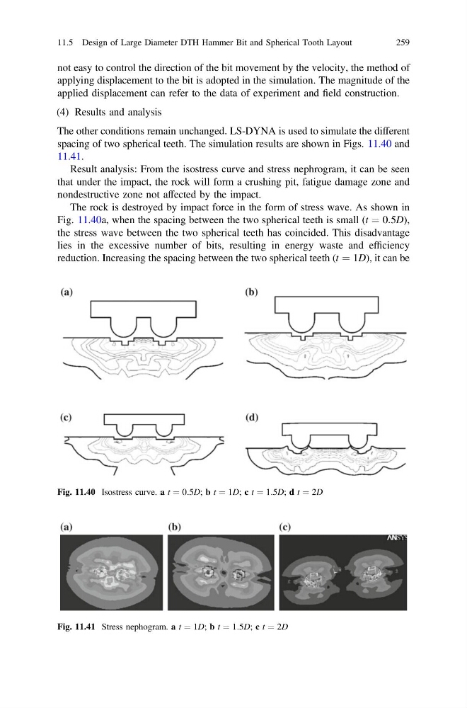
The other conditions remain unchanged. LS-DYNA is used to simulate the different
spacing of two spherical teeth. The simulation results are shown in Figs. 11.40 and
11.41.
Result analysis: From the isostress curve and stress nephrogram, it can be seen
that under the impact, the rock will form a crushing pit, fatigue damage zone and
nondestructive zone not affected by the impact.
The rock is destroyed by impact force in the form of stress wave. As shown in
Fig. 11.40a, when the spacing between the two spherical teeth is small (t ¼ 0:5D),
the stress wave between the two spherical teeth has coincided. This disadvantage
lies in the excessive number of bits, resulting in energy waste and efficiency
reduction. Increasing the spacing between the two spherical teeth (t ¼ 1D), it can be
Fig. 11.40 Isostress curve. a t ¼ 0:5D; b t ¼ 1D; c t ¼ 1:5D; d t ¼ 2D
Fig. 11.41 Stress nephogram. a t ¼ 1D; b t ¼ 1:5D; c t ¼ 2D
11.5 Design of Large Diameter DTH Hammer Bit and Spherical Tooth Layout
259
applying displacement to the bit is adopted in the simulation. The magnitude of the
applied displacement can refer to the data of experiment and field construction.
(4) Results and analysis
The other conditions remain unchanged. LS-DYNA is used to simulate the different
spacing of two spherical teeth. The simulation results are shown in Figs. 11.40 and
11.41.
Result analysis: From the isostress curve and stress nephrogram, it can be seen
that under the impact, the rock will form a crushing pit, fatigue damage zone and
nondestructive zone not affected by the impact.
The rock is destroyed by impact force in the form of stress wave. As shown in
Fig. 11.40a, when the spacing between the two spherical teeth is small (t ¼ 0:5D),
the stress wave between the two spherical teeth has coincided. This disadvantage
lies in the excessive number of bits, resulting in energy waste and efficiency
reduction. Increasing the spacing between the two spherical teeth (t ¼ 1D), it can be
Fig. 11.40 Isostress curve. a t ¼ 0:5D; b t ¼ 1D; c t ¼ 1:5D; d t ¼ 2D
Fig. 11.41 Stress nephogram. a t ¼ 1D; b t ¼ 1:5D; c t ¼ 2D
11.5 Design of Large Diameter DTH Hammer Bit and Spherical Tooth Layout
259