

stage (front chamber intake and rear chamber exhaust), and then the velocity begins
to decrease, and hits the bit at the end of this stage.
In order to select the most reasonable intake pressure p 0 for the large diameter
pneumatic DTH hammer, the performances of DTH hammer impactors with p 0 of
1:7; 1:4; 1:1 and 0:8 MPa were compared.
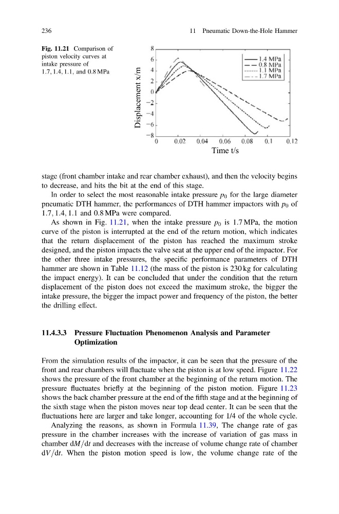
As shown in Fig. 11.21, when the intake pressure p 0 is 1:7 MPa, the motion
curve of the piston is interrupted at the end of the return motion, which indicates
that the return displacement of the piston has reached the maximum stroke
designed, and the piston impacts the valve seat at the upper end of the impactor. For
the other three intake pressures, the specific performance parameters of DTH
hammer are shown in Table 11.12 (the mass of the piston is 230 kg for calculating
the impact energy). It can be concluded that under the condition that the return
displacement of the piston does not exceed the maximum stroke, the bigger the
intake pressure, the bigger the impact power and frequency of the piston, the better
the drilling effect.
11.4.3.3 Pressure Fluctuation Phenomenon Analysis and Parameter
Optimization
From the simulation results of the impactor, it can be seen that the pressure of the
front and rear chambers will fluctuate when the piston is at low speed. Figure 11.22
shows the pressure of the front chamber at the beginning of the return motion. The
pressure fluctuates briefly at the beginning of the piston motion. Figure 11.23
shows the back chamber pressure at the end of the fifth stage and at the beginning of
the sixth stage when the piston moves near top dead center. It can be seen that the
fluctuations here are larger and take longer, accounting for 1/4 of the whole cycle.
Analyzing the reasons, as shown in Formula 11.39, The change rate of gas
pressure in the chamber increases with the increase of variation of gas mass in
chamber dM=dt and decreases with the increase of volume change rate of chamber
dV=dt. When the piston motion speed is low, the volume change rate of the
Displacement x/m
Time t/s
Fig. 11.21 Comparison of
piston velocity curves at
intake pressure of
1:7; 1:4; 1:1; and 0:8 MPa
236
11 Pneumatic Down-the-Hole Hammer
to decrease, and hits the bit at the end of this stage.
In order to select the most reasonable intake pressure p 0 for the large diameter
pneumatic DTH hammer, the performances of DTH hammer impactors with p 0 of
1:7; 1:4; 1:1 and 0:8 MPa were compared.
As shown in Fig. 11.21, when the intake pressure p 0 is 1:7 MPa, the motion
curve of the piston is interrupted at the end of the return motion, which indicates
that the return displacement of the piston has reached the maximum stroke
designed, and the piston impacts the valve seat at the upper end of the impactor. For
the other three intake pressures, the specific performance parameters of DTH
hammer are shown in Table 11.12 (the mass of the piston is 230 kg for calculating
the impact energy). It can be concluded that under the condition that the return
displacement of the piston does not exceed the maximum stroke, the bigger the
intake pressure, the bigger the impact power and frequency of the piston, the better
the drilling effect.
11.4.3.3 Pressure Fluctuation Phenomenon Analysis and Parameter
Optimization
From the simulation results of the impactor, it can be seen that the pressure of the
front and rear chambers will fluctuate when the piston is at low speed. Figure 11.22
shows the pressure of the front chamber at the beginning of the return motion. The
pressure fluctuates briefly at the beginning of the piston motion. Figure 11.23
shows the back chamber pressure at the end of the fifth stage and at the beginning of
the sixth stage when the piston moves near top dead center. It can be seen that the
fluctuations here are larger and take longer, accounting for 1/4 of the whole cycle.
Analyzing the reasons, as shown in Formula 11.39, The change rate of gas
pressure in the chamber increases with the increase of variation of gas mass in
chamber dM=dt and decreases with the increase of volume change rate of chamber
dV=dt. When the piston motion speed is low, the volume change rate of the
Displacement x/m
Time t/s
Fig. 11.21 Comparison of
piston velocity curves at
intake pressure of
1:7; 1:4; 1:1; and 0:8 MPa
236
11 Pneumatic Down-the-Hole Hammer