

11.4.3.2 Comparison of Performance Parameters of DTH Hammer
Under Different Intake Pressure
Intake pressure p 0 is an important factor to determine the impact energy and
frequency, and therefore is also the main parameter affecting drilling speed. In large
diameter drilling in complex formations, the appropriate supply pressure should be
selected to achieve drilling efficiency. For the large diameter DTH hammer
impactor designed in this paper, the initial matching intake pressure of the impactor
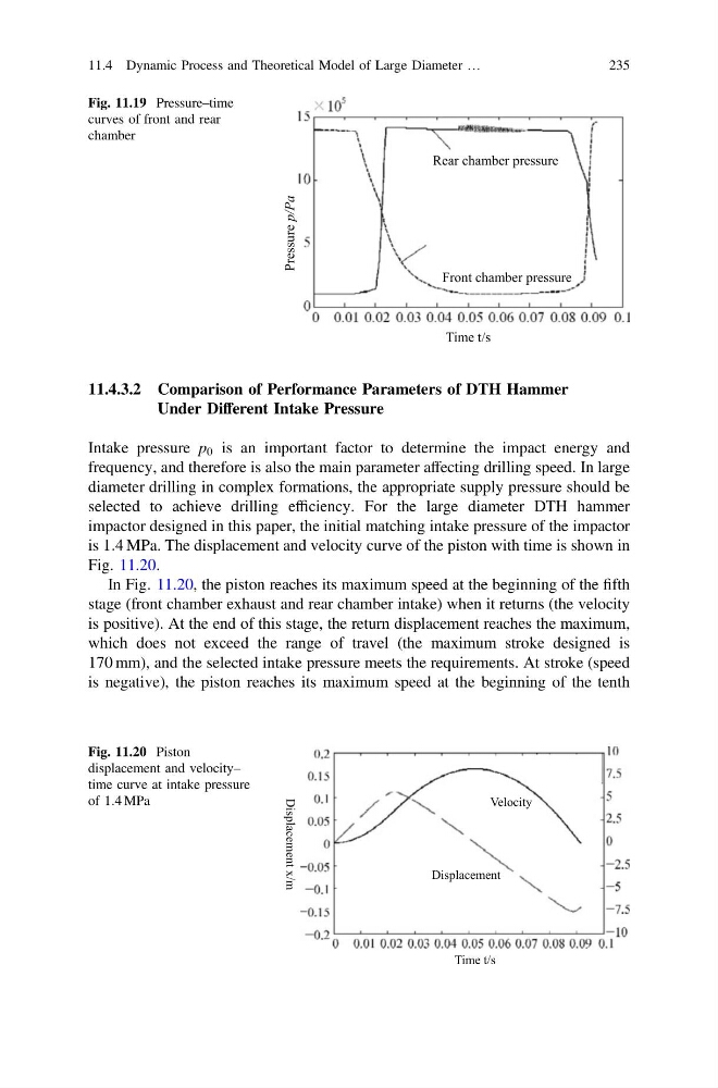
is 1:4 MPa. The displacement and velocity curve of the piston with time is shown in
Fig. 11.20.
In Fig. 11.20, the piston reaches its maximum speed at the beginning of the fifth
stage (front chamber exhaust and rear chamber intake) when it returns (the velocity
is positive). At the end of this stage, the return displacement reaches the maximum,
which does not exceed the range of travel (the maximum stroke designed is
170 mm), and the selected intake pressure meets the requirements. At stroke (speed
is negative), the piston reaches its maximum speed at the beginning of the tenth
Pressure p/Pa
Front chamber pressure
Rear chamber pressure
Time t/s
Fig. 11.19 Pressure–time
curves of front and rear
chamber
Velocity
Time t/s
Displacement x/m
Displacement
Fig. 11.20 Piston
displacement and velocity–
time curve at intake pressure
of 1:4 MPa
11.4 Dynamic Process and Theoretical Model of Large Diameter …
235
Under Different Intake Pressure
Intake pressure p 0 is an important factor to determine the impact energy and
frequency, and therefore is also the main parameter affecting drilling speed. In large
diameter drilling in complex formations, the appropriate supply pressure should be
selected to achieve drilling efficiency. For the large diameter DTH hammer
impactor designed in this paper, the initial matching intake pressure of the impactor
is 1:4 MPa. The displacement and velocity curve of the piston with time is shown in
Fig. 11.20.
In Fig. 11.20, the piston reaches its maximum speed at the beginning of the fifth
stage (front chamber exhaust and rear chamber intake) when it returns (the velocity
is positive). At the end of this stage, the return displacement reaches the maximum,
which does not exceed the range of travel (the maximum stroke designed is
170 mm), and the selected intake pressure meets the requirements. At stroke (speed
is negative), the piston reaches its maximum speed at the beginning of the tenth
Pressure p/Pa
Front chamber pressure
Rear chamber pressure
Time t/s
Fig. 11.19 Pressure–time
curves of front and rear
chamber
Velocity
Time t/s
Displacement x/m
Displacement
Fig. 11.20 Piston
displacement and velocity–
time curve at intake pressure
of 1:4 MPa
11.4 Dynamic Process and Theoretical Model of Large Diameter …
235