

When the pressure at the exit section of the nozzle is exactly equal to the external
backpressure, the gas expands completely in the nozzle, the nozzle is in the optimum
expansion state, the nozzle throat reaches the critical state, and the outlet flow is
supersonic. When the fluid flows out of the nozzle, it neither expands nor compresses, and it is a parallel jet. The flow velocity in the nozzle is supersonic. When
there is a small disturbance in the external environment, the propagation velocity of
the disturbance (sound velocity) is less than the flow velocity, and the disturbance
cannot enter the nozzle. When the inlet pressure of nozzle is increased on the basis of
the optimum expansion state, the outlet pressure of nozzle is also increased, which
makes the outlet pressure stronger than the external backpressure. At this time, the
gas is not fully expanded in the nozzle and its energy is not fully utilized. After the
gas flows out of the nozzle, it will continue to expand until the pressure equals the
external backpressure. At this time, the disturbance outside the nozzle cannot be
conversely transmitted to the nozzle. Contrary to under expansion state, when the
inlet pressure of nozzle is reduced on the basis of the optimal expansion state, the
outlet pressure of nozzle decreases, which makes the outlet pressure less than the
external backpressure. At this time, the excessive expansion of gas in the nozzle will
produce shock wave at the nozzle outlet, which may affect the flow in the nozzle.
In order to make the flow in nozzle free from external interference, p e ! p a must
be satisfied, which is the mechanical condition of nozzle design. As shown in
Fig. 10.16, the pressure variation at nozzle axis under different inlet pressures is
illustrated. The inlet pressure of 1 is 9:8 MPa, and the pressure decreases continuously in the nozzle and decreases to 0:13 MPa at the outlet. The inlet pressure of 2
is 6:1 MPa. At x ¼ 25:5 lm, the pressure decreases to 0:1 MPa. From here on, the
flow in the nozzle will be disturbed by the external pressure. When the external
pressure is 0, the pressure at the outlet of the nozzle can be reduced to 0:07 MPa.
The inlet pressure of 3 is 2:8 MPa, and the pressure decreases to 0:1 MPa at
x ¼ 23 lm. From here on, the flow in the nozzle will be disturbed by external
pressure, and then the pressure in the nozzle will continue to decrease to zero.
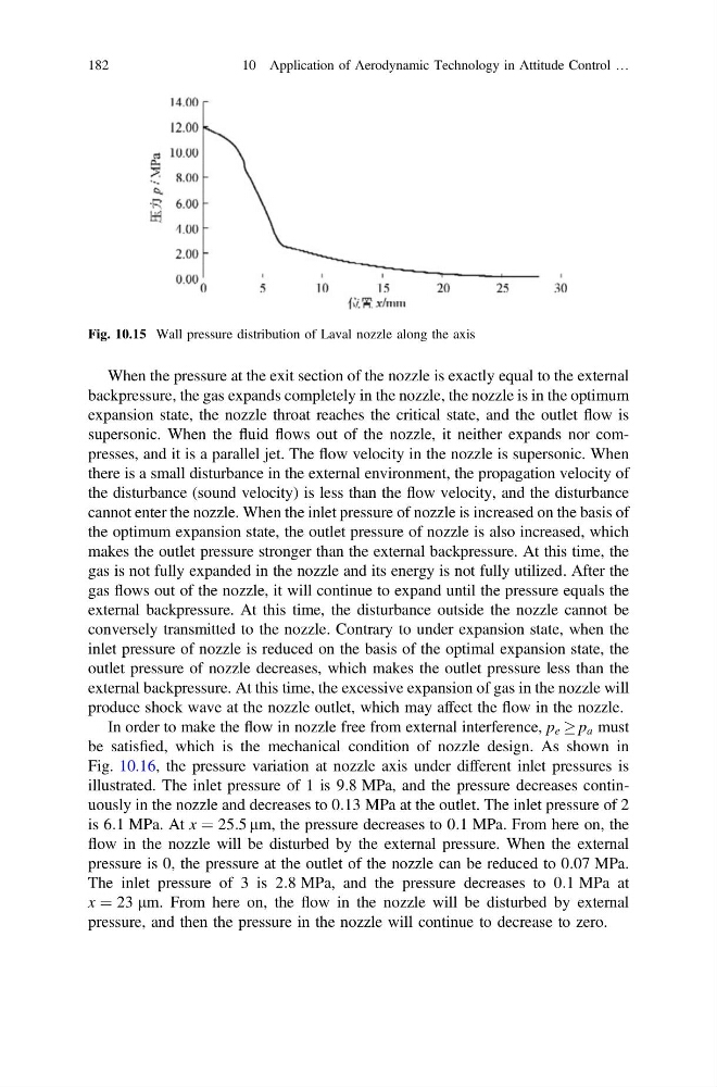
Fig. 10.15 Wall pressure distribution of Laval nozzle along the axis
182
10 Application of Aerodynamic Technology in Attitude Control …
backpressure, the gas expands completely in the nozzle, the nozzle is in the optimum
expansion state, the nozzle throat reaches the critical state, and the outlet flow is
supersonic. When the fluid flows out of the nozzle, it neither expands nor compresses, and it is a parallel jet. The flow velocity in the nozzle is supersonic. When
there is a small disturbance in the external environment, the propagation velocity of
the disturbance (sound velocity) is less than the flow velocity, and the disturbance
cannot enter the nozzle. When the inlet pressure of nozzle is increased on the basis of
the optimum expansion state, the outlet pressure of nozzle is also increased, which
makes the outlet pressure stronger than the external backpressure. At this time, the
gas is not fully expanded in the nozzle and its energy is not fully utilized. After the
gas flows out of the nozzle, it will continue to expand until the pressure equals the
external backpressure. At this time, the disturbance outside the nozzle cannot be
conversely transmitted to the nozzle. Contrary to under expansion state, when the
inlet pressure of nozzle is reduced on the basis of the optimal expansion state, the
outlet pressure of nozzle decreases, which makes the outlet pressure less than the
external backpressure. At this time, the excessive expansion of gas in the nozzle will
produce shock wave at the nozzle outlet, which may affect the flow in the nozzle.
In order to make the flow in nozzle free from external interference, p e ! p a must
be satisfied, which is the mechanical condition of nozzle design. As shown in
Fig. 10.16, the pressure variation at nozzle axis under different inlet pressures is
illustrated. The inlet pressure of 1 is 9:8 MPa, and the pressure decreases continuously in the nozzle and decreases to 0:13 MPa at the outlet. The inlet pressure of 2
is 6:1 MPa. At x ¼ 25:5 lm, the pressure decreases to 0:1 MPa. From here on, the
flow in the nozzle will be disturbed by the external pressure. When the external
pressure is 0, the pressure at the outlet of the nozzle can be reduced to 0:07 MPa.
The inlet pressure of 3 is 2:8 MPa, and the pressure decreases to 0:1 MPa at
x ¼ 23 lm. From here on, the flow in the nozzle will be disturbed by external
pressure, and then the pressure in the nozzle will continue to decrease to zero.
Fig. 10.15 Wall pressure distribution of Laval nozzle along the axis
182
10 Application of Aerodynamic Technology in Attitude Control …