

10.1.3 Experiments and Analysis
10.1.3.1 Design Scheme
Aiming at the overall requirement of lateral force control device proposed by whole
system for the control cabin, the current control cabin adopts the gas scheme. After
ignition by the gas generator, the lateral thrust is generated by the high-temperature
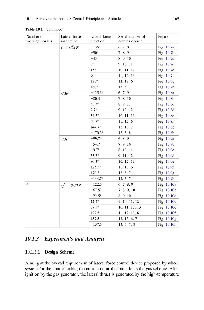
Table 10.1 (continued)
Number of
working nozzles
Lateral force
magnitude
Lateral force
direction
Serial number of
nozzles opened
Figure
3
ð1 þ
ffiffi ffi
2
p Þ F
−135°
6, 7, 8
Fig. 10.7a
−90°
7, 8, 9
Fig. 10.7b
−45°
8, 9, 10
Fig. 10.7c
0°
9, 10, 11
Fig. 10.7d
45°
10, 11, 12
Fig. 10.7e
90°
11, 12, 13
Fig. 10.7f
135°
12, 13, 6
Fig. 10.7g
180°
13, 6, 7
Fig. 10.7h
ffiffi ffi
3
p
F
−125.3°
6, 7, 9
Fig. 10.8a
−80.3°
7, 8, 10
Fig. 10.8b
35.3°
8, 9, 11
Fig. 10.8c
9.7°
9, 10, 12
Fig. 10.8d
54.7°
10, 11, 13
Fig. 10.8e
99.7°
11, 12, 6
Fig. 10.8f
144.7°
12, 13, 7
Fig. 10.8g
−170.3°
13, 6, 8
Fig. 10.8h
ffiffi ffi
3
p
F
−99.7°
6, 8, 9
Fig. 10.9a
−54.7°
7, 9, 10
Fig. 10.9b
−9.7°
8, 10, 11
Fig. 10.9c
35.3°
9, 11, 12
Fig. 10.9d
80.3°
10, 12, 13
Fig. 10.9e
125.3°
11, 13, 6
Fig. 10.9f
170.3°
12, 6, 7
Fig. 10.9g
−144.7°
13, 6, 7
Fig. 10.9h
4
ffiffiffiffiffiffiffiffiffiffiffiffiffiffiffiffiffi
4 þ 2
ffiffi ffi
2
p
p
F
−122.5°
6, 7, 8, 9
Fig. 10.10a
−67.5°
7, 8, 9, 10
Fig. 10.10b
−22.5°
8, 9, 10, 11
Fig. 10.10c
22.5°
9, 10, 11, 12
Fig. 10.10d
67.5°
10, 11, 12, 13
Fig. 10.10e
122.5°
11, 12, 13, 6
Fig. 10.10f
157.5°
12, 13, 6, 7
Fig. 10.10g
−157.5°
13, 6, 7, 8
Fig. 10.10h
10.1 Aerodynamic Attitude Control Principle and Attitude …
169
10.1.3.1 Design Scheme
Aiming at the overall requirement of lateral force control device proposed by whole
system for the control cabin, the current control cabin adopts the gas scheme. After
ignition by the gas generator, the lateral thrust is generated by the high-temperature
Table 10.1 (continued)
Number of
working nozzles
Lateral force
magnitude
Lateral force
direction
Serial number of
nozzles opened
Figure
3
ð1 þ
ffiffi ffi
2
p Þ F
−135°
6, 7, 8
Fig. 10.7a
−90°
7, 8, 9
Fig. 10.7b
−45°
8, 9, 10
Fig. 10.7c
0°
9, 10, 11
Fig. 10.7d
45°
10, 11, 12
Fig. 10.7e
90°
11, 12, 13
Fig. 10.7f
135°
12, 13, 6
Fig. 10.7g
180°
13, 6, 7
Fig. 10.7h
ffiffi ffi
3
p
F
−125.3°
6, 7, 9
Fig. 10.8a
−80.3°
7, 8, 10
Fig. 10.8b
35.3°
8, 9, 11
Fig. 10.8c
9.7°
9, 10, 12
Fig. 10.8d
54.7°
10, 11, 13
Fig. 10.8e
99.7°
11, 12, 6
Fig. 10.8f
144.7°
12, 13, 7
Fig. 10.8g
−170.3°
13, 6, 8
Fig. 10.8h
ffiffi ffi
3
p
F
−99.7°
6, 8, 9
Fig. 10.9a
−54.7°
7, 9, 10
Fig. 10.9b
−9.7°
8, 10, 11
Fig. 10.9c
35.3°
9, 11, 12
Fig. 10.9d
80.3°
10, 12, 13
Fig. 10.9e
125.3°
11, 13, 6
Fig. 10.9f
170.3°
12, 6, 7
Fig. 10.9g
−144.7°
13, 6, 7
Fig. 10.9h
4
ffiffiffiffiffiffiffiffiffiffiffiffiffiffiffiffiffi
4 þ 2
ffiffi ffi
2
p
p
F
−122.5°
6, 7, 8, 9
Fig. 10.10a
−67.5°
7, 8, 9, 10
Fig. 10.10b
−22.5°
8, 9, 10, 11
Fig. 10.10c
22.5°
9, 10, 11, 12
Fig. 10.10d
67.5°
10, 11, 12, 13
Fig. 10.10e
122.5°
11, 12, 13, 6
Fig. 10.10f
157.5°
12, 13, 6, 7
Fig. 10.10g
−157.5°
13, 6, 7, 8
Fig. 10.10h
10.1 Aerodynamic Attitude Control Principle and Attitude …
169