

10.1.2 Lateral Force Analysis of Attitude Control
Eight jet reaction force control devices are distributed radially in parallel on missile
aircraft. When different nozzles are opened, the magnitude and direction of the
resultant force are different. Combining with Fig. 10.1b, the direction of nozzle
No. 6 is taken as 0
direction, and the number and direction of nozzles opened by
solenoid valve are different, and different lateral forces will be obtained. As shown
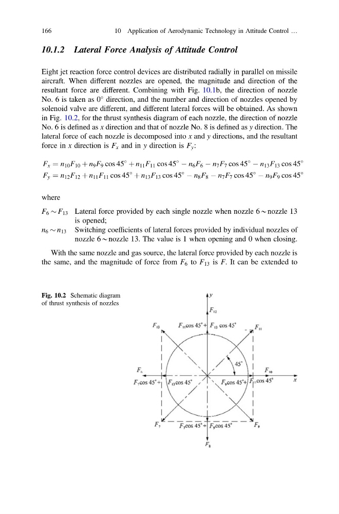
in Fig. 10.2, for the thrust synthesis diagram of each nozzle, the direction of nozzle
No. 6 is defined as x direction and that of nozzle No. 8 is defined as y direction. The
lateral force of each nozzle is decomposed into x and y directions, and the resultant
force in x direction is F x and in y direction is F y :
F x ¼ n 10 F 10 þ n 9 F 9 cos 45
þ n 11 F 11 cos 45
À n 6 F 6 À n 7 F 7 cos 45
À n 13 F 13 cos 45
F y ¼ n 12 F 12 þ n 11 F 11 cos 45
þ n 13 F 13 cos 45
À n 8 F 8 À n 7 F 7 cos 45
À n 9 F 9 cos 45
where
F 6 $ F 13 Lateral force provided by each single nozzle when nozzle 6*nozzle 13
is opened;
n 6 $ n 13 Switching coefficients of lateral forces provided by individual nozzles of
nozzle 6*nozzle 13. The value is 1 when opening and 0 when closing.
With the same nozzle and gas source, the lateral force provided by each nozzle is
the same, and the magnitude of force from F 6 to F 13 is F. It can be extended to
Fig. 10.2 Schematic diagram
of thrust synthesis of nozzles
166
10 Application of Aerodynamic Technology in Attitude Control …
Eight jet reaction force control devices are distributed radially in parallel on missile
aircraft. When different nozzles are opened, the magnitude and direction of the
resultant force are different. Combining with Fig. 10.1b, the direction of nozzle
No. 6 is taken as 0
direction, and the number and direction of nozzles opened by
solenoid valve are different, and different lateral forces will be obtained. As shown
in Fig. 10.2, for the thrust synthesis diagram of each nozzle, the direction of nozzle
No. 6 is defined as x direction and that of nozzle No. 8 is defined as y direction. The
lateral force of each nozzle is decomposed into x and y directions, and the resultant
force in x direction is F x and in y direction is F y :
F x ¼ n 10 F 10 þ n 9 F 9 cos 45
þ n 11 F 11 cos 45
À n 6 F 6 À n 7 F 7 cos 45
À n 13 F 13 cos 45
F y ¼ n 12 F 12 þ n 11 F 11 cos 45
þ n 13 F 13 cos 45
À n 8 F 8 À n 7 F 7 cos 45
À n 9 F 9 cos 45
where
F 6 $ F 13 Lateral force provided by each single nozzle when nozzle 6*nozzle 13
is opened;
n 6 $ n 13 Switching coefficients of lateral forces provided by individual nozzles of
nozzle 6*nozzle 13. The value is 1 when opening and 0 when closing.
With the same nozzle and gas source, the lateral force provided by each nozzle is
the same, and the magnitude of force from F 6 to F 13 is F. It can be extended to
Fig. 10.2 Schematic diagram
of thrust synthesis of nozzles
166
10 Application of Aerodynamic Technology in Attitude Control …