

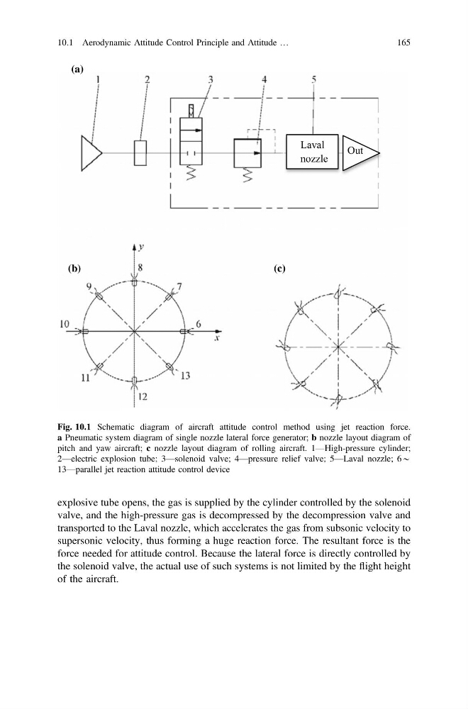
explosive tube opens, the gas is supplied by the cylinder controlled by the solenoid
valve, and the high-pressure gas is decompressed by the decompression valve and
transported to the Laval nozzle, which accelerates the gas from subsonic velocity to
supersonic velocity, thus forming a huge reaction force. The resultant force is the
force needed for attitude control. Because the lateral force is directly controlled by
the solenoid valve, the actual use of such systems is not limited by the flight height
of the aircraft.
Laval
nozzle
Out
(a)
(c)
(b)
Fig. 10.1 Schematic diagram of aircraft attitude control method using jet reaction force.
a Pneumatic system diagram of single nozzle lateral force generator; b nozzle layout diagram of
pitch and yaw aircraft; c nozzle layout diagram of rolling aircraft. 1—High-pressure cylinder;
2—electric explosion tube; 3—solenoid valve; 4—pressure relief valve; 5—Laval nozzle; 6*
13—parallel jet reaction attitude control device
10.1 Aerodynamic Attitude Control Principle and Attitude …
165
valve, and the high-pressure gas is decompressed by the decompression valve and
transported to the Laval nozzle, which accelerates the gas from subsonic velocity to
supersonic velocity, thus forming a huge reaction force. The resultant force is the
force needed for attitude control. Because the lateral force is directly controlled by
the solenoid valve, the actual use of such systems is not limited by the flight height
of the aircraft.
Laval
nozzle
Out
(a)
(c)
(b)
Fig. 10.1 Schematic diagram of aircraft attitude control method using jet reaction force.
a Pneumatic system diagram of single nozzle lateral force generator; b nozzle layout diagram of
pitch and yaw aircraft; c nozzle layout diagram of rolling aircraft. 1—High-pressure cylinder;
2—electric explosion tube; 3—solenoid valve; 4—pressure relief valve; 5—Laval nozzle; 6*
13—parallel jet reaction attitude control device
10.1 Aerodynamic Attitude Control Principle and Attitude …
165