

The above equation is the flow process equation of adiabatic process. By using
the equation of state pV ¼ RT of ideal gas, it can be derived from the above
equation
ðp 2 =p 1 Þ
kÀ1
ð
Þ=k ¼ T 2 =T 1
T 2 =T 1 ¼ V 2 =V 1
ð
Þ
kÀ1
ð
Þ
where
k Adiabatic index, k ¼ C p =C V .
In this way, the state parameters of the gas at the nozzle exit can be derived from
the two state parameters at the nozzle inlet. However, due to various mechanical
losses in the actual process of airflow, it is obviously inaccurate to make engineering calculations according to the abovementioned equations. Therefore,
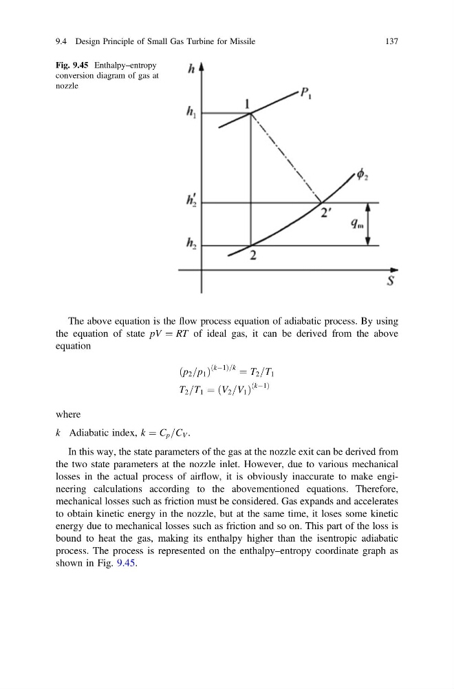
mechanical losses such as friction must be considered. Gas expands and accelerates
to obtain kinetic energy in the nozzle, but at the same time, it loses some kinetic
energy due to mechanical losses such as friction and so on. This part of the loss is
bound to heat the gas, making its enthalpy higher than the isentropic adiabatic
process. The process is represented on the enthalpy–entropy coordinate graph as
shown in Fig. 9.45.
Fig. 9.45 Enthalpy–entropy
conversion diagram of gas at
nozzle
9.4 Design Principle of Small Gas Turbine for Missile
137
the equation of state pV ¼ RT of ideal gas, it can be derived from the above
equation
ðp 2 =p 1 Þ
kÀ1
ð
Þ=k ¼ T 2 =T 1
T 2 =T 1 ¼ V 2 =V 1
ð
Þ
kÀ1
ð
Þ
where
k Adiabatic index, k ¼ C p =C V .
In this way, the state parameters of the gas at the nozzle exit can be derived from
the two state parameters at the nozzle inlet. However, due to various mechanical
losses in the actual process of airflow, it is obviously inaccurate to make engineering calculations according to the abovementioned equations. Therefore,
mechanical losses such as friction must be considered. Gas expands and accelerates
to obtain kinetic energy in the nozzle, but at the same time, it loses some kinetic
energy due to mechanical losses such as friction and so on. This part of the loss is
bound to heat the gas, making its enthalpy higher than the isentropic adiabatic
process. The process is represented on the enthalpy–entropy coordinate graph as
shown in Fig. 9.45.
Fig. 9.45 Enthalpy–entropy
conversion diagram of gas at
nozzle
9.4 Design Principle of Small Gas Turbine for Missile
137