

383
Hybrid Vehicles
modulation ring. When the modulating ring is fabricated as a stationary
body, it offers fixed-ratio variable speed transmission as governed by
p
ω = −
2
ω = −G ω ,
1
2
r 2
p 1
where ω 1 , ω 2 are the rotational speeds of the outer rotor and inner rotor
respectively, G r is the so-called gear ratio, and the minus sign indicates that
the two rotors rotate in opposite directions.
In order to achieve the power split, the modulating ring is designed as
another rotational body. Thus, it can offer continuously variable speed transmission, and the corresponding speed relationship is governed by
ω + G ω − (1 + G )ω = 0,
1
r 2
r
3
where ω 3 is the rotational speed of the modulating ring. Without considering
the power losses occurred at the coaxial magnetic gear, it yields
T ω + T ω + T ω = 0,
1 1
2 2
3 3
where T 1 , T 2 , and T 3 are the developed torques on the inner rotor, outer
rotor, and modulating ring, respectively. Consequently, instead of using
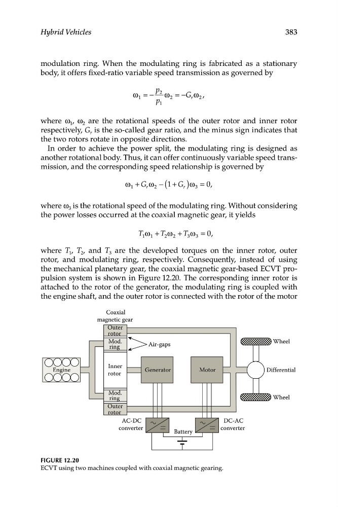
the mechanical planetary gear, the coaxial magnetic gear-based ECVT propulsion system is shown in Figure 12.20. The corresponding inner rotor is
attached to the rotor of the generator, the modulating ring is coupled with
the engine shaft, and the outer rotor is connected with the rotor of the motor
Coaxial
Mod.
ring
Mod.
ring
Inner
rotor
Outer
rotor
Outer
rotor
Generator
Motor
magnetic gear
DC-AC
converter
AC-DC
converter
Battery
Air-gaps
Differential
Wheel
Wheel
Engine
Figure 12.20
ECVT using two machines coupled with coaxial magnetic gearing.
Hybrid Vehicles
modulation ring. When the modulating ring is fabricated as a stationary
body, it offers fixed-ratio variable speed transmission as governed by
p
ω = −
2
ω = −G ω ,
1
2
r 2
p 1
where ω 1 , ω 2 are the rotational speeds of the outer rotor and inner rotor
respectively, G r is the so-called gear ratio, and the minus sign indicates that
the two rotors rotate in opposite directions.
In order to achieve the power split, the modulating ring is designed as
another rotational body. Thus, it can offer continuously variable speed transmission, and the corresponding speed relationship is governed by
ω + G ω − (1 + G )ω = 0,
1
r 2
r
3
where ω 3 is the rotational speed of the modulating ring. Without considering
the power losses occurred at the coaxial magnetic gear, it yields
T ω + T ω + T ω = 0,
1 1
2 2
3 3
where T 1 , T 2 , and T 3 are the developed torques on the inner rotor, outer
rotor, and modulating ring, respectively. Consequently, instead of using
the mechanical planetary gear, the coaxial magnetic gear-based ECVT propulsion system is shown in Figure 12.20. The corresponding inner rotor is
attached to the rotor of the generator, the modulating ring is coupled with
the engine shaft, and the outer rotor is connected with the rotor of the motor
Coaxial
Mod.
ring
Mod.
ring
Inner
rotor
Outer
rotor
Outer
rotor
Generator
Motor
magnetic gear
DC-AC
converter
AC-DC
converter
Battery
Air-gaps
Differential
Wheel
Wheel
Engine
Figure 12.20
ECVT using two machines coupled with coaxial magnetic gearing.