

Fre quency
dP/dθ, histogram
N = 1200 rpm, IT = 35 BTDC, CR = 22, T = 10 Nm
35
30
25
20
15
10
5
0
–5 1
1 0
dP/dθ, bar/degree
100
JME-LPG
Diesel
JME
Diesel-LPG
217
Liquefied Petroleum Gas
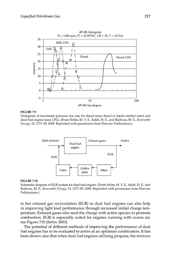
Figure 7.9
Histogram of maximum pressure rise rate for diesel (uses diesel or Jojoba methyl ester) and
dual fuel engine (uses LPG). (From Selim, M. Y. E., Saleh, H. E., and Radwan, M. S., Renewable
Energy, 33, 1173–85, 2008. Reprinted with permission from Elsevier Publications.)
Dual fuel
engine
Inlet mixture
Filter
Orifice
plate
Valve
Exhaust gases
EGR
EGR
Outlet
Figure 7.10
Schematic diagram of EGR system for dual fuel engine. (From Selim, M. Y. E., Saleh, H. E., and
Radwan, M. S., Renewable Energy, 33, 1173–85, 2008. Reprinted with permission from Elsevier
Publications.)
to hot exhaust gas recirculation (EGR) in dual fuel engines can also help
in improving light load performance through increased initial charge temperature. Exhaust gases also seed the charge with active species to promote
combustion. EGR is especially suited for engines running with excess air,
see Figure 7.10 (Selim 2003).
The potential of different methods of improving the performance of dual
fuel engines has to be evaluated to arrive at an optimum combination. It has
been shown also that when dual fuel engines utilizing propane, the mixture
dP/dθ, histogram
N = 1200 rpm, IT = 35 BTDC, CR = 22, T = 10 Nm
35
30
25
20
15
10
5
0
–5 1
1 0
dP/dθ, bar/degree
100
JME-LPG
Diesel
JME
Diesel-LPG
217
Liquefied Petroleum Gas
Figure 7.9
Histogram of maximum pressure rise rate for diesel (uses diesel or Jojoba methyl ester) and
dual fuel engine (uses LPG). (From Selim, M. Y. E., Saleh, H. E., and Radwan, M. S., Renewable
Energy, 33, 1173–85, 2008. Reprinted with permission from Elsevier Publications.)
Dual fuel
engine
Inlet mixture
Filter
Orifice
plate
Valve
Exhaust gases
EGR
EGR
Outlet
Figure 7.10
Schematic diagram of EGR system for dual fuel engine. (From Selim, M. Y. E., Saleh, H. E., and
Radwan, M. S., Renewable Energy, 33, 1173–85, 2008. Reprinted with permission from Elsevier
Publications.)
to hot exhaust gas recirculation (EGR) in dual fuel engines can also help
in improving light load performance through increased initial charge temperature. Exhaust gases also seed the charge with active species to promote
combustion. EGR is especially suited for engines running with excess air,
see Figure 7.10 (Selim 2003).
The potential of different methods of improving the performance of dual
fuel engines has to be evaluated to arrive at an optimum combination. It has
been shown also that when dual fuel engines utilizing propane, the mixture