

209
Liquefied Petroleum Gas
• Mechanically controlled LPG carburetion systems (first generation)
• Electronically controlled LPG carburetion systems (second generation)
• LPG injection systems (third generation)
In countries where vehicles are not required to meet any emission standards,
conventional LPG systems are used. A typical conventional LPG system is
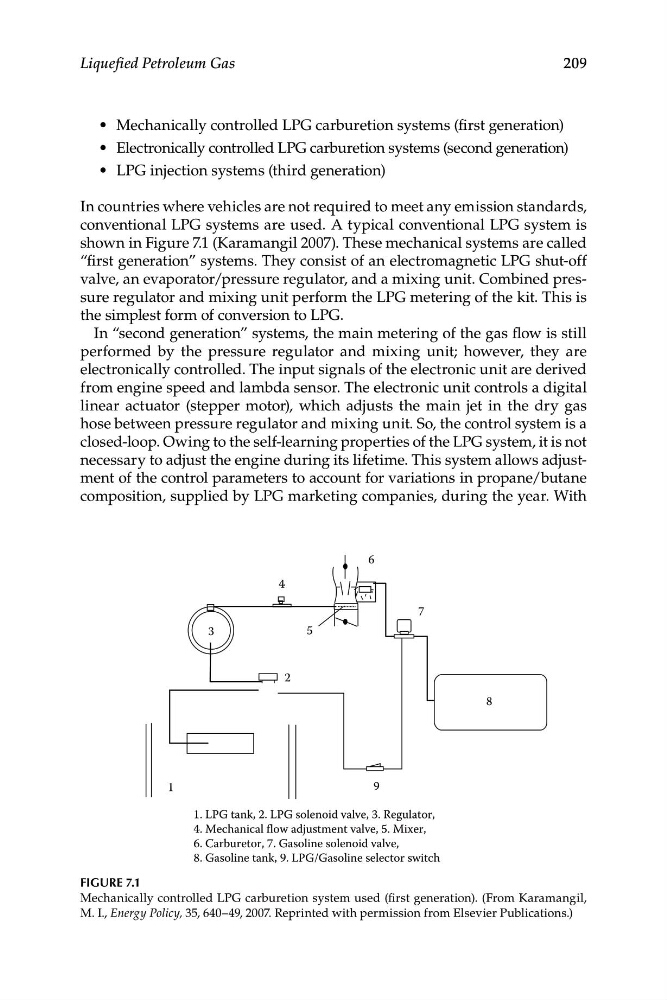
shown in Figure 7.1 (Karamangil 2007). These mechanical systems are called
“first generation” systems. They consist of an electromagnetic LPG shut-off
valve, an evaporator/pressure regulator, and a mixing unit. Combined pressure regulator and mixing unit perform the LPG metering of the kit. This is
the simplest form of conversion to LPG.
In “second generation” systems, the main metering of the gas flow is still
performed by the pressure regulator and mixing unit; however, they are
electronically controlled. The input signals of the electronic unit are derived
from engine speed and lambda sensor. The electronic unit controls a digital
linear actuator (stepper motor), which adjusts the main jet in the dry gas
hose between pressure regulator and mixing unit. So, the control system is a
closed-loop. Owing to the self-learning properties of the LPG system, it is not
necessary to adjust the engine during its lifetime. This system allows adjustment of the control parameters to account for variations in propane/butane
composition, supplied by LPG marketing companies, during the year. With
1
2
8
9
7
6
5
4
3
1. LPG tank, 2. LPG solenoid valve, 3. Regulator,
4. Mechanical flow adjustment valve, 5. Mixer,
6. Carburetor, 7. Gasoline solenoid valve,
8. Gasoline tank, 9. LPG/Gasoline selector switch
Figure 7.1
Mechanically controlled LPG carburetion system used (first generation). (From Karamangil,
M. I., Energy Policy, 35, 640–49, 2007. Reprinted with permission from Elsevier Publications.)
Liquefied Petroleum Gas
• Mechanically controlled LPG carburetion systems (first generation)
• Electronically controlled LPG carburetion systems (second generation)
• LPG injection systems (third generation)
In countries where vehicles are not required to meet any emission standards,
conventional LPG systems are used. A typical conventional LPG system is
shown in Figure 7.1 (Karamangil 2007). These mechanical systems are called
“first generation” systems. They consist of an electromagnetic LPG shut-off
valve, an evaporator/pressure regulator, and a mixing unit. Combined pressure regulator and mixing unit perform the LPG metering of the kit. This is
the simplest form of conversion to LPG.
In “second generation” systems, the main metering of the gas flow is still
performed by the pressure regulator and mixing unit; however, they are
electronically controlled. The input signals of the electronic unit are derived
from engine speed and lambda sensor. The electronic unit controls a digital
linear actuator (stepper motor), which adjusts the main jet in the dry gas
hose between pressure regulator and mixing unit. So, the control system is a
closed-loop. Owing to the self-learning properties of the LPG system, it is not
necessary to adjust the engine during its lifetime. This system allows adjustment of the control parameters to account for variations in propane/butane
composition, supplied by LPG marketing companies, during the year. With
1
2
8
9
7
6
5
4
3
1. LPG tank, 2. LPG solenoid valve, 3. Regulator,
4. Mechanical flow adjustment valve, 5. Mixer,
6. Carburetor, 7. Gasoline solenoid valve,
8. Gasoline tank, 9. LPG/Gasoline selector switch
Figure 7.1
Mechanically controlled LPG carburetion system used (first generation). (From Karamangil,
M. I., Energy Policy, 35, 640–49, 2007. Reprinted with permission from Elsevier Publications.)