

7 Prediction of Bearing Remaining Useful Life Based on LSTM Network
83
σ
σ
tanh
σ
×
+
×
×
Xt
tanh
Ct-1
ht-1
Ct
ht
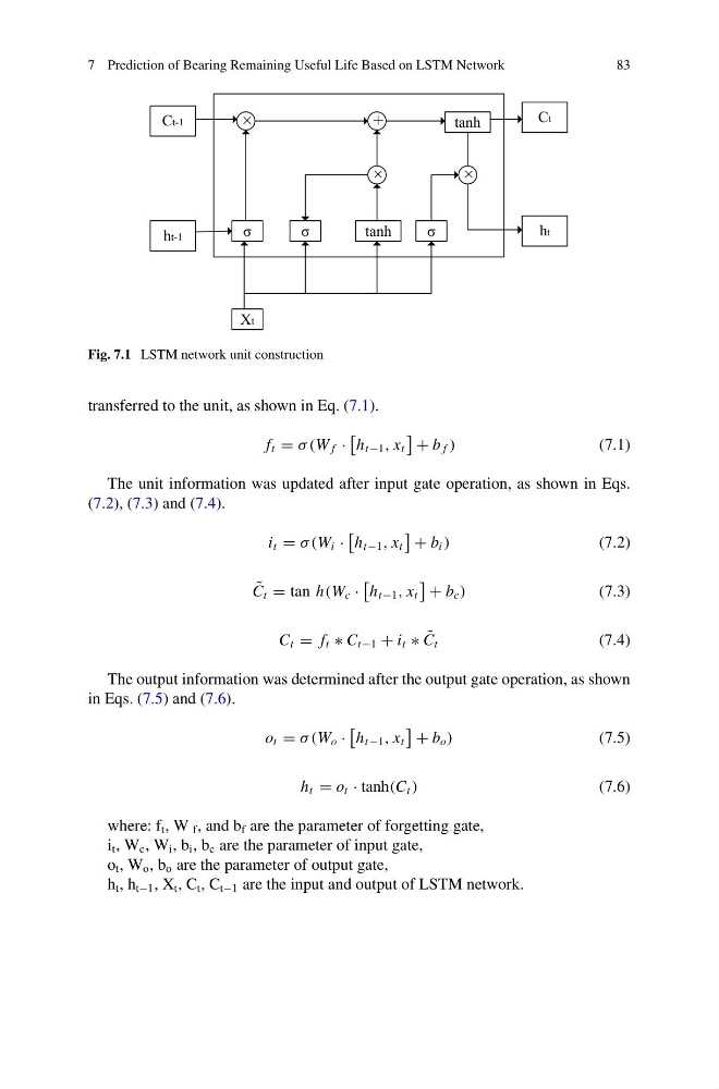
Fig. 7.1 LSTM network unit construction
transferred to the unit, as shown in Eq. (7.1).
f t = σ (W f ·
h t−1 , x t
+ b f )
(7.1)
The unit information was updated after input gate operation, as shown in Eqs.
(7.2), (7.3) and (7.4).
i t = σ (W i ·
h t−1 , x t
+ b i )
(7.2)
˜
C t = tan h(W c ·
h t−1 , x t
+ b c )
(7.3)
C t = f t ∗ C t−1 + i t ∗ ˜
C t
(7.4)
The output information was determined after the output gate operation, as shown
in Eqs. (7.5) and (7.6).
o t = σ (W o ·
h t−1 , x t
+ b o )
(7.5)
h t = o t · tanh(C t )
(7.6)
where: f t , W f , and b f are the parameter of forgetting gate,
i t , W c , W i , b i , b c are the parameter of input gate,
o t , W o , b o are the parameter of output gate,
h t , h t−1 , X t , C t , C t−1 are the input and output of LSTM network.
83
σ
σ
tanh
σ
×
+
×
×
Xt
tanh
Ct-1
ht-1
Ct
ht
Fig. 7.1 LSTM network unit construction
transferred to the unit, as shown in Eq. (7.1).
f t = σ (W f ·
h t−1 , x t
+ b f )
(7.1)
The unit information was updated after input gate operation, as shown in Eqs.
(7.2), (7.3) and (7.4).
i t = σ (W i ·
h t−1 , x t
+ b i )
(7.2)
˜
C t = tan h(W c ·
h t−1 , x t
+ b c )
(7.3)
C t = f t ∗ C t−1 + i t ∗ ˜
C t
(7.4)
The output information was determined after the output gate operation, as shown
in Eqs. (7.5) and (7.6).
o t = σ (W o ·
h t−1 , x t
+ b o )
(7.5)
h t = o t · tanh(C t )
(7.6)
where: f t , W f , and b f are the parameter of forgetting gate,
i t , W c , W i , b i , b c are the parameter of input gate,
o t , W o , b o are the parameter of output gate,
h t , h t−1 , X t , C t , C t−1 are the input and output of LSTM network.