

36
X. Sun et al.
3.3.2 Recast Layer and HAZ
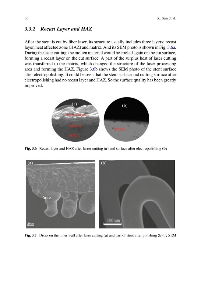
After the stent is cut by fiber laser, its structure usually includes three layers: recast
layer, heat affected zone (HAZ) and matrix. And its SEM photo is shown in Fig. 3.6a.
During the laser cutting, the molten material would be cooled again on the cut surface,
forming a recast layer on the cut surface. A part of the surplus heat of laser cutting
was transferred to the matrix, which changed the structure of the laser processing
area and forming the HAZ. Figure 3.6b shows the SEM photo of the stent surface
after electropolishing. It could be seen that the stent surface and cutting surface after
electropolishing had no recast layer and HAZ. So the surface quality has been greatly
improved.
Matrix
(a)
Recast layer
Matrix
HAZ
(b)
Fig. 3.6 Recast layer and HAZ after laster cutting (a) and surface after electropolishing (b)
(a)
(b)
Dross
Fig. 3.7 Dross on the inner wall after laser cutting (a) and part of stent after polishing (b) by SEM
X. Sun et al.
3.3.2 Recast Layer and HAZ
After the stent is cut by fiber laser, its structure usually includes three layers: recast
layer, heat affected zone (HAZ) and matrix. And its SEM photo is shown in Fig. 3.6a.
During the laser cutting, the molten material would be cooled again on the cut surface,
forming a recast layer on the cut surface. A part of the surplus heat of laser cutting
was transferred to the matrix, which changed the structure of the laser processing
area and forming the HAZ. Figure 3.6b shows the SEM photo of the stent surface
after electropolishing. It could be seen that the stent surface and cutting surface after
electropolishing had no recast layer and HAZ. So the surface quality has been greatly
improved.
Matrix
(a)
Recast layer
Matrix
HAZ
(b)
Fig. 3.6 Recast layer and HAZ after laster cutting (a) and surface after electropolishing (b)
(a)
(b)
Dross
Fig. 3.7 Dross on the inner wall after laser cutting (a) and part of stent after polishing (b) by SEM