

17 The Influence of Pressure Angle of Spur Gears …
211
17.2 Geometric Specifications of the Studied Gears
In this study, a spur gear pair with different pressure angles (14.5°, 17.5°, 20°, 22.5°
and 25°) and the same dedendum (h fp /m n = 1.4) was investigated. A dedendum equal
to 1.4 m n permits the finishing tool to work without interference, while maintaining
the maximum fillet radius and is recommended for high-precision gears transmitting
high torques. It is also suitable for gears with tooth flanks finished by grinding [3].
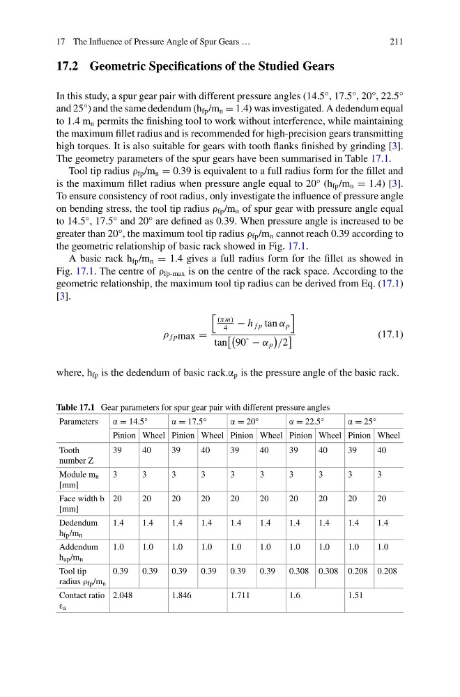
The geometry parameters of the spur gears have been summarised in Table 17.1.
Tool tip radius ρ fp /m n = 0.39 is equivalent to a full radius form for the fillet and
is the maximum fillet radius when pressure angle equal to 20° (h fp /m n = 1.4) [3].
To ensure consistency of root radius, only investigate the influence of pressure angle
on bending stress, the tool tip radius ρ fp /m n of spur gear with pressure angle equal
to 14.5°, 17.5° and 20° are defined as 0.39. When pressure angle is increased to be
greater than 20°, the maximum tool tip radius ρ fp /m n cannot reach 0.39 according to
the geometric relationship of basic rack showed in Fig. 17.1.
A basic rack h fp /m n = 1.4 gives a full radius form for the fillet as showed in
Fig. 17.1. The centre of ρ fp-max is on the centre of the rack space. According to the
geometric relationship, the maximum tool tip radius can be derived from Eq. (17.1)
[3].
ρ f pmax =
(πm)
4
− h f p tan α p
tan
90
◦ − α p
/2
(17.1)
where, h fp is the dedendum of basic rack.α p is the pressure angle of the basic rack.
Table 17.1 Gear parameters for spur gear pair with different pressure angles
Parameters
α = 14.5°
α = 17.5°
α = 20°
α = 22.5°
α = 25°
Pinion Wheel Pinion Wheel Pinion Wheel Pinion Wheel Pinion Wheel
Tooth
number Z
39
40
39
40
39
40
39
40
39
40
Module m n
[mm]
3
3
3
3
3
3
3
3
3
3
Face width b
[mm]
20
20
20
20
20
20
20
20
20
20
Dedendum
h fp /m n
1.4
1.4
1.4
1.4
1.4
1.4
1.4
1.4
1.4
1.4
Addendum
h ap /m n
1.0
1.0
1.0
1.0
1.0
1.0
1.0
1.0
1.0
1.0
Tool tip
radius ρ fp /m n
0.39
0.39
0.39
0.39
0.39
0.39
0.308 0.308 0.208 0.208
Contact ratio
ε α
2.048
1.846
1.711
1.6
1.51
211
17.2 Geometric Specifications of the Studied Gears
In this study, a spur gear pair with different pressure angles (14.5°, 17.5°, 20°, 22.5°
and 25°) and the same dedendum (h fp /m n = 1.4) was investigated. A dedendum equal
to 1.4 m n permits the finishing tool to work without interference, while maintaining
the maximum fillet radius and is recommended for high-precision gears transmitting
high torques. It is also suitable for gears with tooth flanks finished by grinding [3].
The geometry parameters of the spur gears have been summarised in Table 17.1.
Tool tip radius ρ fp /m n = 0.39 is equivalent to a full radius form for the fillet and
is the maximum fillet radius when pressure angle equal to 20° (h fp /m n = 1.4) [3].
To ensure consistency of root radius, only investigate the influence of pressure angle
on bending stress, the tool tip radius ρ fp /m n of spur gear with pressure angle equal
to 14.5°, 17.5° and 20° are defined as 0.39. When pressure angle is increased to be
greater than 20°, the maximum tool tip radius ρ fp /m n cannot reach 0.39 according to
the geometric relationship of basic rack showed in Fig. 17.1.
A basic rack h fp /m n = 1.4 gives a full radius form for the fillet as showed in
Fig. 17.1. The centre of ρ fp-max is on the centre of the rack space. According to the
geometric relationship, the maximum tool tip radius can be derived from Eq. (17.1)
[3].
ρ f pmax =
(πm)
4
− h f p tan α p
tan
90
◦ − α p
/2
(17.1)
where, h fp is the dedendum of basic rack.α p is the pressure angle of the basic rack.
Table 17.1 Gear parameters for spur gear pair with different pressure angles
Parameters
α = 14.5°
α = 17.5°
α = 20°
α = 22.5°
α = 25°
Pinion Wheel Pinion Wheel Pinion Wheel Pinion Wheel Pinion Wheel
Tooth
number Z
39
40
39
40
39
40
39
40
39
40
Module m n
[mm]
3
3
3
3
3
3
3
3
3
3
Face width b
[mm]
20
20
20
20
20
20
20
20
20
20
Dedendum
h fp /m n
1.4
1.4
1.4
1.4
1.4
1.4
1.4
1.4
1.4
1.4
Addendum
h ap /m n
1.0
1.0
1.0
1.0
1.0
1.0
1.0
1.0
1.0
1.0
Tool tip
radius ρ fp /m n
0.39
0.39
0.39
0.39
0.39
0.39
0.308 0.308 0.208 0.208
Contact ratio
ε α
2.048
1.846
1.711
1.6
1.51