

200
S. Zhan et al.
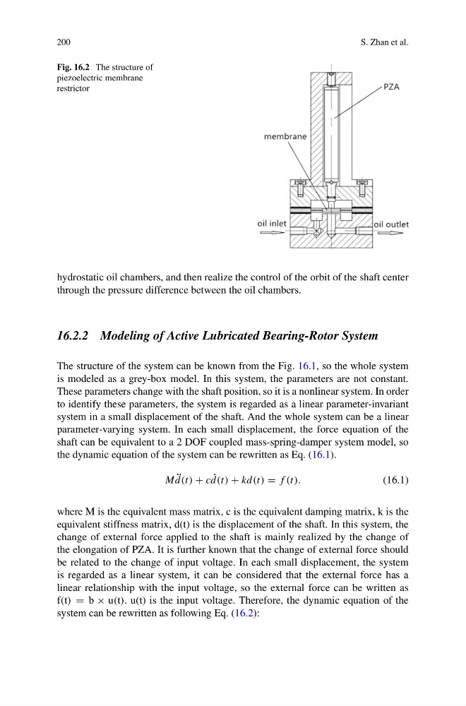
Fig. 16.2 The structure of
piezoelectric membrane
restrictor
hydrostatic oil chambers, and then realize the control of the orbit of the shaft center
through the pressure difference between the oil chambers.
16.2.2 Modeling of Active Lubricated Bearing-Rotor System
The structure of the system can be known from the Fig. 16.1, so the whole system
is modeled as a grey-box model. In this system, the parameters are not constant.
These parameters change with the shaft position, so it is a nonlinear system. In order
to identify these parameters, the system is regarded as a linear parameter-invariant
system in a small displacement of the shaft. And the whole system can be a linear
parameter-varying system. In each small displacement, the force equation of the
shaft can be equivalent to a 2 DOF coupled mass-spring-damper system model, so
the dynamic equation of the system can be rewritten as Eq. (16.1).
M ¨
d(t) + c ˙
d(t) + kd(t) = f (t).
(16.1)
where M is the equivalent mass matrix, c is the equivalent damping matrix, k is the
equivalent stiffness matrix, d(t) is the displacement of the shaft. In this system, the
change of external force applied to the shaft is mainly realized by the change of
the elongation of PZA. It is further known that the change of external force should
be related to the change of input voltage. In each small displacement, the system
is regarded as a linear system, it can be considered that the external force has a
linear relationship with the input voltage, so the external force can be written as
f(t) = b × u(t). u(t) is the input voltage. Therefore, the dynamic equation of the
system can be rewritten as following Eq. (16.2):
S. Zhan et al.
Fig. 16.2 The structure of
piezoelectric membrane
restrictor
hydrostatic oil chambers, and then realize the control of the orbit of the shaft center
through the pressure difference between the oil chambers.
16.2.2 Modeling of Active Lubricated Bearing-Rotor System
The structure of the system can be known from the Fig. 16.1, so the whole system
is modeled as a grey-box model. In this system, the parameters are not constant.
These parameters change with the shaft position, so it is a nonlinear system. In order
to identify these parameters, the system is regarded as a linear parameter-invariant
system in a small displacement of the shaft. And the whole system can be a linear
parameter-varying system. In each small displacement, the force equation of the
shaft can be equivalent to a 2 DOF coupled mass-spring-damper system model, so
the dynamic equation of the system can be rewritten as Eq. (16.1).
M ¨
d(t) + c ˙
d(t) + kd(t) = f (t).
(16.1)
where M is the equivalent mass matrix, c is the equivalent damping matrix, k is the
equivalent stiffness matrix, d(t) is the displacement of the shaft. In this system, the
change of external force applied to the shaft is mainly realized by the change of
the elongation of PZA. It is further known that the change of external force should
be related to the change of input voltage. In each small displacement, the system
is regarded as a linear system, it can be considered that the external force has a
linear relationship with the input voltage, so the external force can be written as
f(t) = b × u(t). u(t) is the input voltage. Therefore, the dynamic equation of the
system can be rewritten as following Eq. (16.2):