

16 Modeling and Parameter Identification for Active Lubricated …
199
system. Firstly, the system is established as a segmented linear model, and the parameters are solved by the error minimization criterion. After obtaining the segmented
parameters, the parameter variation law of the system is obtained by fitting multiple
segmented parameters. Finally, the identification results demonstrate the validity and
accuracy of the proposed method.
16.2 Principle and Modeling of Active Lubricated
Bearing-Rotor System
16.2.1 Principle of Active Bearing Rotor-System
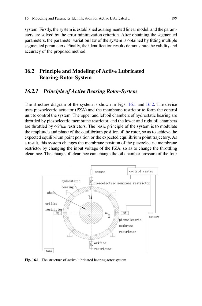
The structure diagram of the system is shown in Figs. 16.1 and 16.2. The device
uses piezoelectric actuator (PZA) and the membrane restrictor to form the control
unit to control the system. The upper and left oil chambers of hydrostatic bearing are
throttled by piezoelectric membrane restrictor, and the lower and right oil chambers
are throttled by orifice restrictors. The basic principle of the system is to modulate
the amplitude and phase of the equilibrium position of the rotor, so as to achieve the
expected equilibrium point position or the expected equilibrium point trajectory. As
a result, this system changes the membrane position of the piezoelectric membrane
restrictor by changing the input voltage of the PZA, so as to change the throttling
clearance. The change of clearance can change the oil chamber pressure of the four
Fig. 16.1 The structure of active lubricated bearing-rotor system
199
system. Firstly, the system is established as a segmented linear model, and the parameters are solved by the error minimization criterion. After obtaining the segmented
parameters, the parameter variation law of the system is obtained by fitting multiple
segmented parameters. Finally, the identification results demonstrate the validity and
accuracy of the proposed method.
16.2 Principle and Modeling of Active Lubricated
Bearing-Rotor System
16.2.1 Principle of Active Bearing Rotor-System
The structure diagram of the system is shown in Figs. 16.1 and 16.2. The device
uses piezoelectric actuator (PZA) and the membrane restrictor to form the control
unit to control the system. The upper and left oil chambers of hydrostatic bearing are
throttled by piezoelectric membrane restrictor, and the lower and right oil chambers
are throttled by orifice restrictors. The basic principle of the system is to modulate
the amplitude and phase of the equilibrium position of the rotor, so as to achieve the
expected equilibrium point position or the expected equilibrium point trajectory. As
a result, this system changes the membrane position of the piezoelectric membrane
restrictor by changing the input voltage of the PZA, so as to change the throttling
clearance. The change of clearance can change the oil chamber pressure of the four
Fig. 16.1 The structure of active lubricated bearing-rotor system