

160
X. Bi et al.
Undamaged shear
model
Delamination preset shear
damage model
Preset
delamination
Composite layer
1 layer
Cohesive layer 1
Composite layer
7 layers
Cohesive layer 2
Composite layer
7 layers
Cohesive layer 3
Composite layer
1 layer
Fixed
Load
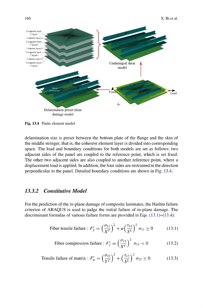
Fig. 13.4 Finite element model
delamination size is preset between the bottom plate of the flange and the skin of
the middle stringer, that is, the cohesive element layer is divided into corresponding
space. The load and boundary conditions for both models are set as follows: two
adjacent sides of the panel are coupled to the reference point, which is set fixed.
The other two adjacent sides are also coupled to another reference point, where a
displacement load is applied. In addition, the four sides are restrained in the direction
perpendicular to the panel. Detailed boundary conditions are shown in Fig. 13.4.
13.3.2 Constitutive Model
For the prediction of the in-plane damage of composite laminates, the Hashin failure
criterion of ABAQUS is used to judge the initial failure of in-plane damage. The
discriminant formulas of various failure forms are provided in Eqs. (13.1)–(13.4):
Fiber tensile failure : F
t
f =
σ 11
X T
2 + α
τ 12
S L
2 σ 11 ≥ 0
(13.1)
Fiber compression failure : F
c
f =
σ 11
X C
2 σ 11 < 0
(13.2)
Tensile failure of matrix : F
t
m =
σ 22
Y T
2 +
τ 12
S L
2 σ 22 ≥ 0
(13.3)
X. Bi et al.
Undamaged shear
model
Delamination preset shear
damage model
Preset
delamination
Composite layer
1 layer
Cohesive layer 1
Composite layer
7 layers
Cohesive layer 2
Composite layer
7 layers
Cohesive layer 3
Composite layer
1 layer
Fixed
Load
Fig. 13.4 Finite element model
delamination size is preset between the bottom plate of the flange and the skin of
the middle stringer, that is, the cohesive element layer is divided into corresponding
space. The load and boundary conditions for both models are set as follows: two
adjacent sides of the panel are coupled to the reference point, which is set fixed.
The other two adjacent sides are also coupled to another reference point, where a
displacement load is applied. In addition, the four sides are restrained in the direction
perpendicular to the panel. Detailed boundary conditions are shown in Fig. 13.4.
13.3.2 Constitutive Model
For the prediction of the in-plane damage of composite laminates, the Hashin failure
criterion of ABAQUS is used to judge the initial failure of in-plane damage. The
discriminant formulas of various failure forms are provided in Eqs. (13.1)–(13.4):
Fiber tensile failure : F
t
f =
σ 11
X T
2 + α
τ 12
S L
2 σ 11 ≥ 0
(13.1)
Fiber compression failure : F
c
f =
σ 11
X C
2 σ 11 < 0
(13.2)
Tensile failure of matrix : F
t
m =
σ 22
Y T
2 +
τ 12
S L
2 σ 22 ≥ 0
(13.3)