

12 Strength Analysis of a Plate Heat Exchanger …
151
pressure is the one corresponding to the last sub-step before the calculation becomes
divergent. In this study, 1 load-step and 100 sub-steps are set for the computation.
About 48hrs are required to finish a computation to get the limit load.
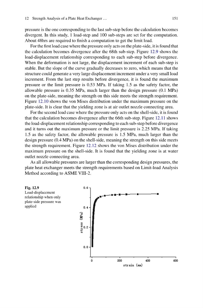
For the first load case where the pressure only acts on the plate-side, it is found that
the calculation becomes divergence after the 68th sub-step. Figure 12.9 shows the
load-displacement relationship corresponding to each sub-step before divergence.
When the deformation is not large, the displacement increment of each sub-step is
stable. But the slope of the curve gradually decreases to zero, which means that the
structure could generate a very large displacement increment under a very small load
increment. From the last step results before divergence, it is found the maximum
pressure or the limit pressure is 0.53 MPa. If taking 1.5 as the safety factor, the
allowable pressure is 0.35 MPa, much larger than the design pressure (0.1 MPa)
on the plate-side, meaning the strength on this side meets the strength requirement.
Figure 12.10 shows the von Mises distribution under the maximum pressure on the
plate-side. It is clear that the yielding zone is at air outlet nozzle connecting area.
For the second load case where the pressure only acts on the shell-side, it is found
that the calculation becomes divergence after the 66th sub-step. Figure 12.11 shows
the load-displacement relationship corresponding to each sub-step before divergence
and it turns out the maximum pressure or the limit pressure is 2.25 MPa. If taking
1.5 as the safety factor, the allowable pressure is 1.5 MPa, much larger than the
design pressure (0.4 MPa) on the shell-side, meaning the strength on this side meets
the strength requirement. Figure 12.12 shows the von Mises distribution under the
maximum pressure on the shell-side. It is found that the yielding zone is at water
outlet nozzle connecting area.
As all allowable pressures are larger than the corresponding design pressures, the
plate heat exchanger meets the strength requirements based on Limit-load Analysis
Method according to ASME VIII-2.
Fig. 12.9
Load-displacement
relationship when only
plate-side pressure was
applied
151
pressure is the one corresponding to the last sub-step before the calculation becomes
divergent. In this study, 1 load-step and 100 sub-steps are set for the computation.
About 48hrs are required to finish a computation to get the limit load.
For the first load case where the pressure only acts on the plate-side, it is found that
the calculation becomes divergence after the 68th sub-step. Figure 12.9 shows the
load-displacement relationship corresponding to each sub-step before divergence.
When the deformation is not large, the displacement increment of each sub-step is
stable. But the slope of the curve gradually decreases to zero, which means that the
structure could generate a very large displacement increment under a very small load
increment. From the last step results before divergence, it is found the maximum
pressure or the limit pressure is 0.53 MPa. If taking 1.5 as the safety factor, the
allowable pressure is 0.35 MPa, much larger than the design pressure (0.1 MPa)
on the plate-side, meaning the strength on this side meets the strength requirement.
Figure 12.10 shows the von Mises distribution under the maximum pressure on the
plate-side. It is clear that the yielding zone is at air outlet nozzle connecting area.
For the second load case where the pressure only acts on the shell-side, it is found
that the calculation becomes divergence after the 66th sub-step. Figure 12.11 shows
the load-displacement relationship corresponding to each sub-step before divergence
and it turns out the maximum pressure or the limit pressure is 2.25 MPa. If taking
1.5 as the safety factor, the allowable pressure is 1.5 MPa, much larger than the
design pressure (0.4 MPa) on the shell-side, meaning the strength on this side meets
the strength requirement. Figure 12.12 shows the von Mises distribution under the
maximum pressure on the shell-side. It is found that the yielding zone is at water
outlet nozzle connecting area.
As all allowable pressures are larger than the corresponding design pressures, the
plate heat exchanger meets the strength requirements based on Limit-load Analysis
Method according to ASME VIII-2.
Fig. 12.9
Load-displacement
relationship when only
plate-side pressure was
applied