

9 Numerical Simulation on the Slab Heat Transfer Behavior …
107
τ gm = 1 − 0.5
a gs + a gw
,
(9.8)
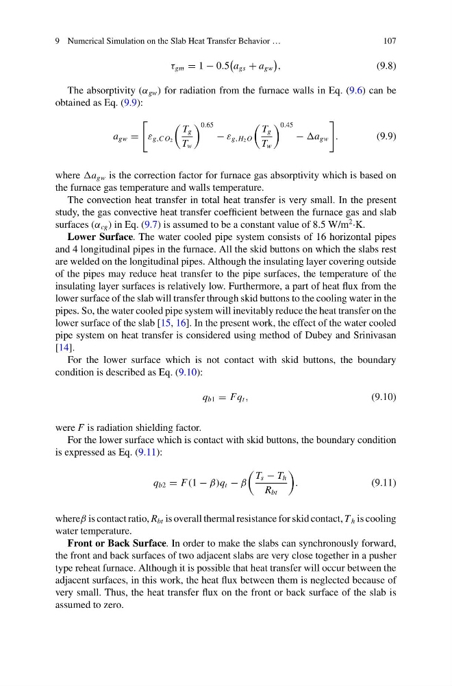
The absorptivity (α gw ) for radiation from the furnace walls in Eq. (9.6) can be
obtained as Eq. (9.9):
a gw =
ε g,C O 2
T g
T w
0.65
− ε g,H 2 O
T g
T w
0.45
− a gw
.
(9.9)
where a gw is the correction factor for furnace gas absorptivity which is based on
the furnace gas temperature and walls temperature.
The convection heat transfer in total heat transfer is very small. In the present
study, the gas convective heat transfer coefficient between the furnace gas and slab
surfaces (α cg ) in Eq. (9.7) is assumed to be a constant value of 8.5 W/m
2 ·K.
Lower Surface. The water cooled pipe system consists of 16 horizontal pipes
and 4 longitudinal pipes in the furnace. All the skid buttons on which the slabs rest
are welded on the longitudinal pipes. Although the insulating layer covering outside
of the pipes may reduce heat transfer to the pipe surfaces, the temperature of the
insulating layer surfaces is relatively low. Furthermore, a part of heat flux from the
lower surface of the slab will transfer through skid buttons to the cooling water in the
pipes. So, the water cooled pipe system will inevitably reduce the heat transfer on the
lower surface of the slab [15, 16]. In the present work, the effect of the water cooled
pipe system on heat transfer is considered using method of Dubey and Srinivasan
[14].
For the lower surface which is not contact with skid buttons, the boundary
condition is described as Eq. (9.10):
q b1 = Fq t ,
(9.10)
were F is radiation shielding factor.
For the lower surface which is contact with skid buttons, the boundary condition
is expressed as Eq. (9.11):
q b2 = F(1 − β)q t − β
T s − T h
R bt
.
(9.11)
whereβ is contact ratio, R bt is overall thermal resistance for skid contact, T h is cooling
water temperature.
Front or Back Surface. In order to make the slabs can synchronously forward,
the front and back surfaces of two adjacent slabs are very close together in a pusher
type reheat furnace. Although it is possible that heat transfer will occur between the
adjacent surfaces, in this work, the heat flux between them is neglected because of
very small. Thus, the heat transfer flux on the front or back surface of the slab is
assumed to zero.
107
τ gm = 1 − 0.5
a gs + a gw
,
(9.8)
The absorptivity (α gw ) for radiation from the furnace walls in Eq. (9.6) can be
obtained as Eq. (9.9):
a gw =
ε g,C O 2
T g
T w
0.65
− ε g,H 2 O
T g
T w
0.45
− a gw
.
(9.9)
where a gw is the correction factor for furnace gas absorptivity which is based on
the furnace gas temperature and walls temperature.
The convection heat transfer in total heat transfer is very small. In the present
study, the gas convective heat transfer coefficient between the furnace gas and slab
surfaces (α cg ) in Eq. (9.7) is assumed to be a constant value of 8.5 W/m
2 ·K.
Lower Surface. The water cooled pipe system consists of 16 horizontal pipes
and 4 longitudinal pipes in the furnace. All the skid buttons on which the slabs rest
are welded on the longitudinal pipes. Although the insulating layer covering outside
of the pipes may reduce heat transfer to the pipe surfaces, the temperature of the
insulating layer surfaces is relatively low. Furthermore, a part of heat flux from the
lower surface of the slab will transfer through skid buttons to the cooling water in the
pipes. So, the water cooled pipe system will inevitably reduce the heat transfer on the
lower surface of the slab [15, 16]. In the present work, the effect of the water cooled
pipe system on heat transfer is considered using method of Dubey and Srinivasan
[14].
For the lower surface which is not contact with skid buttons, the boundary
condition is described as Eq. (9.10):
q b1 = Fq t ,
(9.10)
were F is radiation shielding factor.
For the lower surface which is contact with skid buttons, the boundary condition
is expressed as Eq. (9.11):
q b2 = F(1 − β)q t − β
T s − T h
R bt
.
(9.11)
whereβ is contact ratio, R bt is overall thermal resistance for skid contact, T h is cooling
water temperature.
Front or Back Surface. In order to make the slabs can synchronously forward,
the front and back surfaces of two adjacent slabs are very close together in a pusher
type reheat furnace. Although it is possible that heat transfer will occur between the
adjacent surfaces, in this work, the heat flux between them is neglected because of
very small. Thus, the heat transfer flux on the front or back surface of the slab is
assumed to zero.