

106
M. Feng et al.
resistance calculation model which is a function of the thickness of oxide scale is
adopted to solve the problems. The functions can be represented as Eq. (9.3):
R t =
δ
λ t
(9.3)
where R t is the thermal resistance, δ is the oxide scale thickness, λ t is the conductivity
of the oxide scale as shown in Table 9.1.
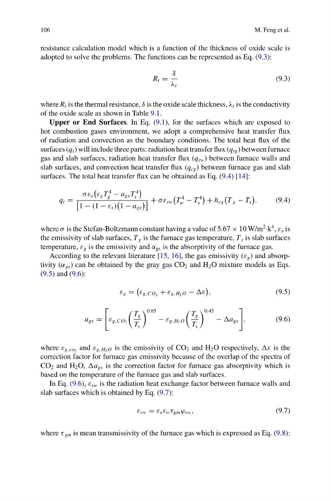
Upper or End Surfaces. In Eq. (9.1), for the surfaces which are exposed to
hot combustion gases environment, we adopt a comprehensive heat transfer flux
of radiation and convection as the boundary conditions. The total heat flux of the
surfaces (q t ) will include three parts: radiation heat transfer flux (q rg ) between furnace
gas and slab surfaces, radiation heat transfer flux (q rw ) between furnace walls and
slab surfaces, and convection heat transfer flux (q cg ) between furnace gas and slab
surfaces. The total heat transfer flux can be obtained as Eq. (9.4) [14]:
q t =
σ ε s
ε g T
4
g − a gs T
4
s
1 − (1 − ε s )
1 − a gs
+ σ ε sw
T
4
w − T
4
s
+ h cg
T g − T s
.
(9.4)
where σ is the Stefan-Boltzmann constant having a value of 5.67 × 10 W/m
2 ·k
4 , ε s is
the emissivity of slab surfaces, T g is the furnace gas temperature, T s is slab surfaces
temperature, ε g is the emissivity and α gs is the absorptivity of the furnace gas.
According to the relevant literature [15, 16], the gas emissivity (ε g ) and absorptivity (α gs ) can be obtained by the gray gas CO 2 and H 2 O mixture models as Eqs.
(9.5) and (9.6):
ε g =
ε g,C O 2 + ε g,H 2 O − ε
,
(9.5)
a gs =
ε g,C O 2
T g
T s
0.65
− ε g,H 2 O
T g
T s
0.45
− a gs
,
(9.6)
where ε g,co 2 and ε g,H 2 O is the emissivity of CO 2 and H 2 O respectively, ε is the
correction factor for furnace gas emissivity because of the overlap of the spectra of
CO 2 and H 2 O, a gs is the correction factor for furnace gas absorptivity which is
based on the temperature of the furnace gas and slab surfaces.
In Eq. (9.6), ε sw is the radiation heat exchange factor between furnace walls and
slab surfaces which is obtained by Eq. (9.7):
ε sw = ε s ε w τ gm ϕ sw ,
(9.7)
where τ gm is mean transmissivity of the furnace gas which is expressed as Eq. (9.8):
M. Feng et al.
resistance calculation model which is a function of the thickness of oxide scale is
adopted to solve the problems. The functions can be represented as Eq. (9.3):
R t =
δ
λ t
(9.3)
where R t is the thermal resistance, δ is the oxide scale thickness, λ t is the conductivity
of the oxide scale as shown in Table 9.1.
Upper or End Surfaces. In Eq. (9.1), for the surfaces which are exposed to
hot combustion gases environment, we adopt a comprehensive heat transfer flux
of radiation and convection as the boundary conditions. The total heat flux of the
surfaces (q t ) will include three parts: radiation heat transfer flux (q rg ) between furnace
gas and slab surfaces, radiation heat transfer flux (q rw ) between furnace walls and
slab surfaces, and convection heat transfer flux (q cg ) between furnace gas and slab
surfaces. The total heat transfer flux can be obtained as Eq. (9.4) [14]:
q t =
σ ε s
ε g T
4
g − a gs T
4
s
1 − (1 − ε s )
1 − a gs
+ σ ε sw
T
4
w − T
4
s
+ h cg
T g − T s
.
(9.4)
where σ is the Stefan-Boltzmann constant having a value of 5.67 × 10 W/m
2 ·k
4 , ε s is
the emissivity of slab surfaces, T g is the furnace gas temperature, T s is slab surfaces
temperature, ε g is the emissivity and α gs is the absorptivity of the furnace gas.
According to the relevant literature [15, 16], the gas emissivity (ε g ) and absorptivity (α gs ) can be obtained by the gray gas CO 2 and H 2 O mixture models as Eqs.
(9.5) and (9.6):
ε g =
ε g,C O 2 + ε g,H 2 O − ε
,
(9.5)
a gs =
ε g,C O 2
T g
T s
0.65
− ε g,H 2 O
T g
T s
0.45
− a gs
,
(9.6)
where ε g,co 2 and ε g,H 2 O is the emissivity of CO 2 and H 2 O respectively, ε is the
correction factor for furnace gas emissivity because of the overlap of the spectra of
CO 2 and H 2 O, a gs is the correction factor for furnace gas absorptivity which is
based on the temperature of the furnace gas and slab surfaces.
In Eq. (9.6), ε sw is the radiation heat exchange factor between furnace walls and
slab surfaces which is obtained by Eq. (9.7):
ε sw = ε s ε w τ gm ϕ sw ,
(9.7)
where τ gm is mean transmissivity of the furnace gas which is expressed as Eq. (9.8):