

104
M. Feng et al.
Table 9.2 Volume Compositions of gas in the furnace (%)
CO 2
H 2 O
O 2
N 2
19.3
12.1
2.3
66.3
Table 9.3 Temperature at measurement location
Distance from the entrance [m]
7.40
11.10
12.21
15.73
16.65
18.00
Temperature (K)
775
876
946
1110
1197
1272
Distance from the entrance (m)
21.83
22.20
25.90
31.08
35.33
37.00
Temperature (K)
1517
1523
1578
1633
1663
1668
9.3 Mathematical Model
9.3.1 Heat Conduction Equation
We are selecting a single slab as research object and are following its movement when
it is traveling from entrance to exit of the reheating furnace. According to geometry
symmetry, only half of a single slab is taken as calculation zone. Unlike some of
the other models [13, 14], the geometric model is not including the oxide scale
thickness. The influence of oxide scale to heat transfer of the slab surface has been
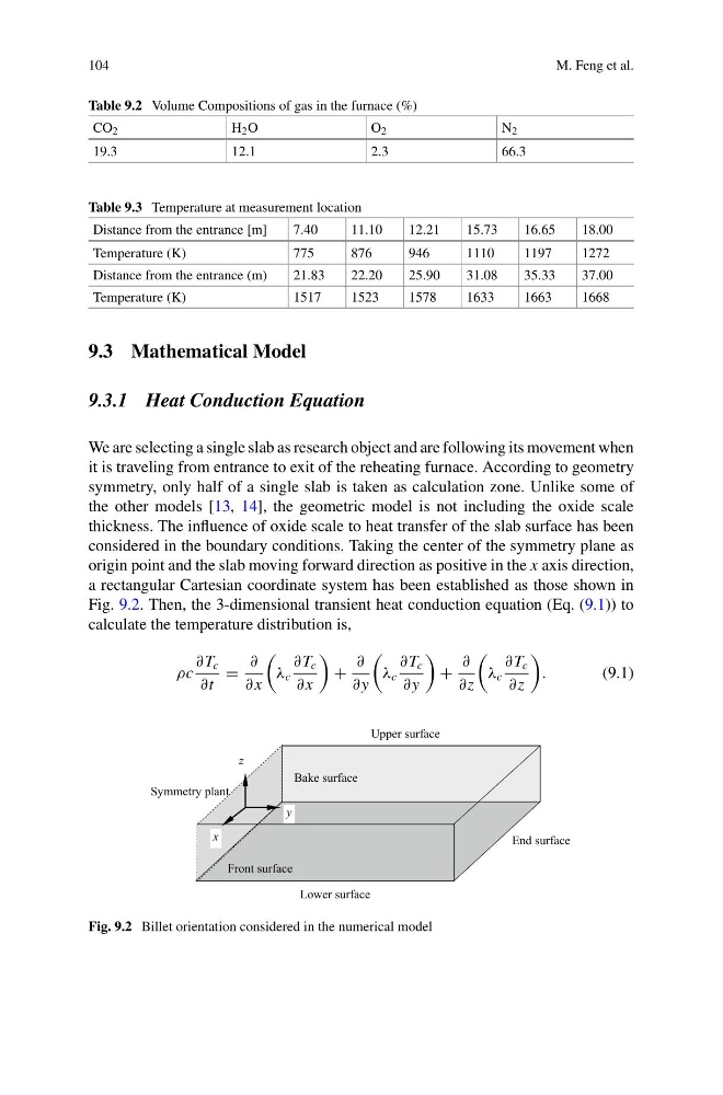
considered in the boundary conditions. Taking the center of the symmetry plane as
origin point and the slab moving forward direction as positive in the x axis direction,
a rectangular Cartesian coordinate system has been established as those shown in
Fig. 9.2. Then, the 3-dimensional transient heat conduction equation (Eq. (9.1)) to
calculate the temperature distribution is,
ρc
∂ T c
∂t
=
∂
∂ x
λ c
∂ T c
∂ x
+
∂
∂ y
λ c
∂ T c
∂ y
+
∂
∂z
λ c
∂ T c
∂z
.
(9.1)
Lower surface
Bake surface
Upper surface
End surface
Front surface
Symmetry plant
y
z
x
Fig. 9.2 Billet orientation considered in the numerical model
M. Feng et al.
Table 9.2 Volume Compositions of gas in the furnace (%)
CO 2
H 2 O
O 2
N 2
19.3
12.1
2.3
66.3
Table 9.3 Temperature at measurement location
Distance from the entrance [m]
7.40
11.10
12.21
15.73
16.65
18.00
Temperature (K)
775
876
946
1110
1197
1272
Distance from the entrance (m)
21.83
22.20
25.90
31.08
35.33
37.00
Temperature (K)
1517
1523
1578
1633
1663
1668
9.3 Mathematical Model
9.3.1 Heat Conduction Equation
We are selecting a single slab as research object and are following its movement when
it is traveling from entrance to exit of the reheating furnace. According to geometry
symmetry, only half of a single slab is taken as calculation zone. Unlike some of
the other models [13, 14], the geometric model is not including the oxide scale
thickness. The influence of oxide scale to heat transfer of the slab surface has been
considered in the boundary conditions. Taking the center of the symmetry plane as
origin point and the slab moving forward direction as positive in the x axis direction,
a rectangular Cartesian coordinate system has been established as those shown in
Fig. 9.2. Then, the 3-dimensional transient heat conduction equation (Eq. (9.1)) to
calculate the temperature distribution is,
ρc
∂ T c
∂t
=
∂
∂ x
λ c
∂ T c
∂ x
+
∂
∂ y
λ c
∂ T c
∂ y
+
∂
∂z
λ c
∂ T c
∂z
.
(9.1)
Lower surface
Bake surface
Upper surface
End surface
Front surface
Symmetry plant
y
z
x
Fig. 9.2 Billet orientation considered in the numerical model