

9 Numerical Simulation on the Slab Heat Transfer Behavior …
103
32 m
Heating zone
Upper burner
Exhaust
Slab
Lower burner
5.6 m
1.2 m
0.4 m
Water cooled pipe
Pusher
(a)
(b)
Preheating zone
Soaking zone
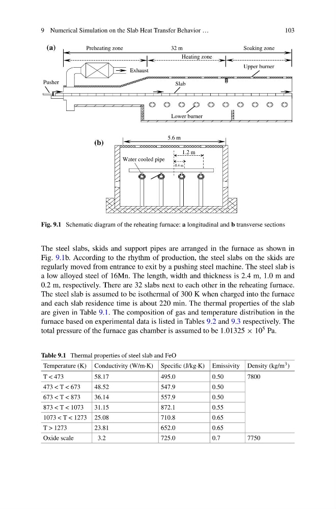
Fig. 9.1 Schematic diagram of the reheating furnace: a longitudinal and b transverse sections
The steel slabs, skids and support pipes are arranged in the furnace as shown in
Fig. 9.1b. According to the rhythm of production, the steel slabs on the skids are
regularly moved from entrance to exit by a pushing steel machine. The steel slab is
a low alloyed steel of 16Mn. The length, width and thickness is 2.4 m, 1.0 m and
0.2 m, respectively. There are 32 slabs next to each other in the reheating furnace.
The steel slab is assumed to be isothermal of 300 K when charged into the furnace
and each slab residence time is about 220 min. The thermal properties of the slab
are given in Table 9.1. The composition of gas and temperature distribution in the
furnace based on experimental data is listed in Tables 9.2 and 9.3 respectively. The
total pressure of the furnace gas chamber is assumed to be 1.01325 × 10
5 Pa.
Table 9.1 Thermal properties of steel slab and FeO
Temperature (K) Conductivity (W/m·K) Specific (J/kg·K) Emissivity Density (kg/m 3 )
T < 473
58.17
495.0
0.50
7800
473 < T < 673
48.52
547.9
0.50
673 < T < 873
36.14
557.9
0.50
873 < T < 1073
31.15
872.1
0.55
1073 < T < 1273 25.08
710.8
0.65
T > 1273
23.81
652.0
0.65
Oxide scale
3.2
725.0
0.7
7750
103
32 m
Heating zone
Upper burner
Exhaust
Slab
Lower burner
5.6 m
1.2 m
0.4 m
Water cooled pipe
Pusher
(a)
(b)
Preheating zone
Soaking zone
Fig. 9.1 Schematic diagram of the reheating furnace: a longitudinal and b transverse sections
The steel slabs, skids and support pipes are arranged in the furnace as shown in
Fig. 9.1b. According to the rhythm of production, the steel slabs on the skids are
regularly moved from entrance to exit by a pushing steel machine. The steel slab is
a low alloyed steel of 16Mn. The length, width and thickness is 2.4 m, 1.0 m and
0.2 m, respectively. There are 32 slabs next to each other in the reheating furnace.
The steel slab is assumed to be isothermal of 300 K when charged into the furnace
and each slab residence time is about 220 min. The thermal properties of the slab
are given in Table 9.1. The composition of gas and temperature distribution in the
furnace based on experimental data is listed in Tables 9.2 and 9.3 respectively. The
total pressure of the furnace gas chamber is assumed to be 1.01325 × 10
5 Pa.
Table 9.1 Thermal properties of steel slab and FeO
Temperature (K) Conductivity (W/m·K) Specific (J/kg·K) Emissivity Density (kg/m 3 )
T < 473
58.17
495.0
0.50
7800
473 < T < 673
48.52
547.9
0.50
673 < T < 873
36.14
557.9
0.50
873 < T < 1073
31.15
872.1
0.55
1073 < T < 1273 25.08
710.8
0.65
T > 1273
23.81
652.0
0.65
Oxide scale
3.2
725.0
0.7
7750