

8 Uncertainty Quantification of Spray Nozzle Fatigue …
95
the head should be at least 0.0582 m and 0.732 m, respectively. Then the actual
extension length is 0.08 m and 0.803 m respectively.
The types of loads considered include self-weight, design external loads, LLSE,
thermal expansion loads, and normal and upset condition transients. In thermal analysis, the transient temperature is applied to the inner surface, and other surfaces that
are not in contact with water or steam are subjected to adiabatic boundary conditions.
In the stress analysis, internal pressure is applied to the inner surface of the structure,
and the external mechanical load and hydrostatic end force generated by the internal
pressure are applied to the top of the extension of the nozzle. And a circumferential
and vertical displacement constraint is applied on the bottom of the lower cylinder
of the model.
8.3 Result and Discussion
In this paper, section No. 3 is taken as an example to carry out calculations. From
the point of view of the pressure, the wall thickness of section No. 3 should be as
thick as possible, while from the perspective of thermal stress, in order to avoid
excessive thermal gradient of section No. 3, which will greatly affect its fatigue
performance, its thickness should be reduced if necessary. Therefore, in order to
achieve the balance between the two schemes in the structural design, it is necessary
to carry out quantitative study of the transient load uncertainty, including the pressure
and temperature, thus calculating the sensitivity of parameters to the fatigue strength
using design transient and allowable cycle numbers. Finally, suggestions from the
point of view of mechanics can be proposed for structural design and optimization
according to the calculation results.
When the fatigue analysis is carried out to the pressurizer spray nozzle in normal
and upset conditions, a total of 40 transients are involved in the fatigue calculation,
and the fatigue usage of the inner point of section No. 3 is calculated to be 0.37851.
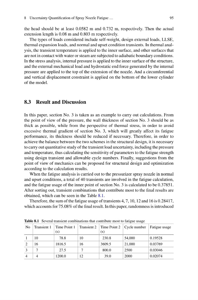
After sorting out, transient combinations that contribute most to the final results are
obtained, which can be seen in the Table 8.1.
Therefore, the sum of the fatigue usage of transients 4, 7, 10, 12 and 16 is 0.28417,
which accounts for 75.08% of the final result. In this paper, randomness is introduced
Table 8.1 Several transient combinations that contribute most to fatigue usage
No Transient 1 Time Point 1
(s)
Transient 2 Time Point 2
(s)
Cycle number Fatigue usage
1
10
78.8
10
230.8
54,000
0.19528
2
16
1816.5
16
3609.5
21,000
0.03769
3
7
27.5
7
800.0
2500
0.03046
4
4
1200.0
12
39.0
2000
0.02074
95
the head should be at least 0.0582 m and 0.732 m, respectively. Then the actual
extension length is 0.08 m and 0.803 m respectively.
The types of loads considered include self-weight, design external loads, LLSE,
thermal expansion loads, and normal and upset condition transients. In thermal analysis, the transient temperature is applied to the inner surface, and other surfaces that
are not in contact with water or steam are subjected to adiabatic boundary conditions.
In the stress analysis, internal pressure is applied to the inner surface of the structure,
and the external mechanical load and hydrostatic end force generated by the internal
pressure are applied to the top of the extension of the nozzle. And a circumferential
and vertical displacement constraint is applied on the bottom of the lower cylinder
of the model.
8.3 Result and Discussion
In this paper, section No. 3 is taken as an example to carry out calculations. From
the point of view of the pressure, the wall thickness of section No. 3 should be as
thick as possible, while from the perspective of thermal stress, in order to avoid
excessive thermal gradient of section No. 3, which will greatly affect its fatigue
performance, its thickness should be reduced if necessary. Therefore, in order to
achieve the balance between the two schemes in the structural design, it is necessary
to carry out quantitative study of the transient load uncertainty, including the pressure
and temperature, thus calculating the sensitivity of parameters to the fatigue strength
using design transient and allowable cycle numbers. Finally, suggestions from the
point of view of mechanics can be proposed for structural design and optimization
according to the calculation results.
When the fatigue analysis is carried out to the pressurizer spray nozzle in normal
and upset conditions, a total of 40 transients are involved in the fatigue calculation,
and the fatigue usage of the inner point of section No. 3 is calculated to be 0.37851.
After sorting out, transient combinations that contribute most to the final results are
obtained, which can be seen in the Table 8.1.
Therefore, the sum of the fatigue usage of transients 4, 7, 10, 12 and 16 is 0.28417,
which accounts for 75.08% of the final result. In this paper, randomness is introduced
Table 8.1 Several transient combinations that contribute most to fatigue usage
No Transient 1 Time Point 1
(s)
Transient 2 Time Point 2
(s)
Cycle number Fatigue usage
1
10
78.8
10
230.8
54,000
0.19528
2
16
1816.5
16
3609.5
21,000
0.03769
3
7
27.5
7
800.0
2500
0.03046
4
4
1200.0
12
39.0
2000
0.02074